Grinding machine
A grinding wheel and bolt technology, applied in the field of grinding machines, can solve the problems of poor safety performance, troublesome use, inability to grind, etc., and achieve the effect of safe use
Inactive Publication Date: 2013-02-20
SUZHOU BLUE KING MACHINE TOOL TECH CO LTD
View PDF6 Cites 7 Cited by
- Summary
- Abstract
- Description
- Claims
- Application Information
AI Technical Summary
Problems solved by technology
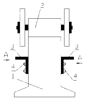
[0002] At present, the grinding wheel machine is generally composed of the grinding head of the grinding wheel machine installed and fixed on the base. When grinding the workpiece, the workpiece is generally held in hand and directly contacts the grinding wheel of the grinding wheel grinding head. Therefore, there are defects such as troublesome use and poor safety performance. , in particular, it is impossible to perform more precise grinding on workpieces that require a certain thickness.
Method used
View moreImage
Smart ImageViewing Examples
Examples
Embodiment Construction
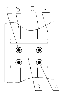
[0010] A grinder, comprising: grinder head (1), base (2), right-angle bent plate (3), T-shaped head bolts (4), characterized in that: the grinder head (1) is installed and fixed on On the top of the base (2), vertical T-slots (5) are made on both sides of the grinder base (2), and T-head bolts ( 4), the right-angle bent plate (3) is installed and fixed on both sides of the base (2) through T-head bolts (4).
Login to View More PUM
 Abstract
A grinding machine is characterized in that on the basis of an existing grinding machine structure, vertical T type grooves are arranged on two sides of a grinding machine base, T type cap bolts are arranged in the T type grooves arranged on two sides of the base, and right angle bended plates are fixed at two sides of the bases through the T type cap bolts. By means of the technical scheme, during workpiece grinding, workpieces can be supported onto the right angle bended plates, simultaneously, in grinding workpieces with specific thicknesses, only the upper planes of the right angle bended plates are required to be adjusted to a specific distance at the downmost end of a grinding wheel, and placing the workpieces between the grinding wheel and the right angle bended plates. Therefore, the grinding machine has the advantages of being safe in use and convenient and in particular has accurate grinding on the workpieces with certain thickness.
Description
technical field [0001] The invention relates to a grinder and belongs to the technical field of electromechanical equipment. Background technique [0002] At present, the grinding wheel machine is generally composed of the grinding head of the grinding wheel machine installed and fixed on the base. When grinding the workpiece, the workpiece is generally held in hand and directly contacts the grinding wheel of the grinding wheel grinding head. Therefore, there are defects such as troublesome use and poor safety performance. , in particular, it is impossible to perform more accurate grinding on workpieces that require a certain thickness. Contents of the invention [0003] The purpose of the present invention is to provide a new type of grinder aiming at the above-mentioned defects existing in the existing grinder. The above-mentioned defects existing in the existing grinder are overcome. [0004] The technical solution adopted by the present invention to achie...
Claims
Login to View More Application Information
Patent Timeline
 Patent Type & Authority Applications(China)
IPC IPC(8): B24B27/00
Inventor 孙生强
Owner SUZHOU BLUE KING MACHINE TOOL TECH CO LTD
Features
- R&D
- Intellectual Property
- Life Sciences
- Materials
- Tech Scout
- Unparalleled Data Quality
- Higher Quality Content
- 60% Fewer Hallucinations
Learn More Browse by: Latest US Patents, China's latest patents, Technical Efficacy Thesaurus, Application Domain, Technology Topic, Popular Technical Reports.
© 2025 PatSnap. All rights reserved.Legal|Privacy policy|Modern Slavery Act Transparency Statement|Sitemap|About US| Contact US: help@patsnap.com


