
Rotor slot grinding machine

A technology of rotor groove and grinding machine, which is applied in the direction of grinding machine, grinding bed, grinding machine parts, etc., can solve the problems of difficult positioning, the inability of the rotor groove to accurately correspond to the grinding wheel, and the wear of the rotor, so as to achieve reasonable structural layout and high machining efficiency. High efficiency and guaranteed accuracy

Active Publication Date: 2017-09-22
绍兴松菱机床有限公司
View PDF5 Cites 0 Cited by
  • Summary
  • Abstract
  • Description
  • Claims
  • Application Information

AI Technical Summary

Problems solved by technology

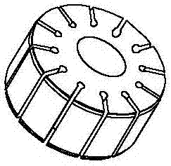
[0002] like figure 1 The rotors shown are widely used in products such as vane pumps, automotive steering pumps, and automotive air-conditioning compressor rotors. The key precision of the rotor is the flatness of the two sides of the radial grooves on the outer peripheral surface of the rotor. Therefore, in the rotor processing After forming, it is necessary to grind the groove of the rotor. The existing rotor groove grinding machine grinds the rotor groove through the grinding wheel, and then the existing rotor is difficult to locate during the processing, and the rotor workpiece often appears in the feeding process. The groove cannot correspond to the grinding wheel precisely, the grinding wheel cannot be inserted into the rotor groove, and the grinding wheel is easy to touch the peripheral surface of the rotor, causing the rotor to wear

Method used


Image

  • Rotor slot grinding machine
  • Rotor slot grinding machine
  • Rotor slot grinding machine

Examples


Embodiment Construction

[0026] Specific embodiments of the present invention will be described in detail below in conjunction with the accompanying drawings.

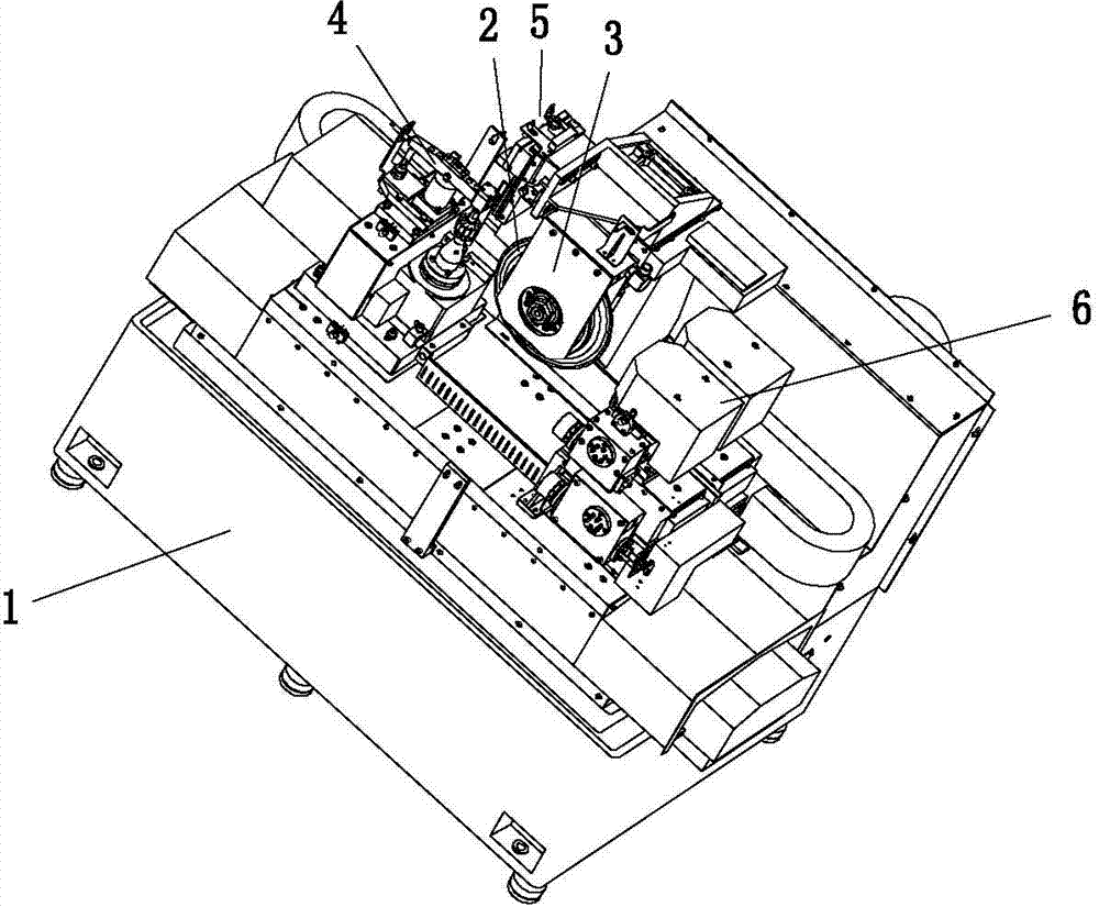
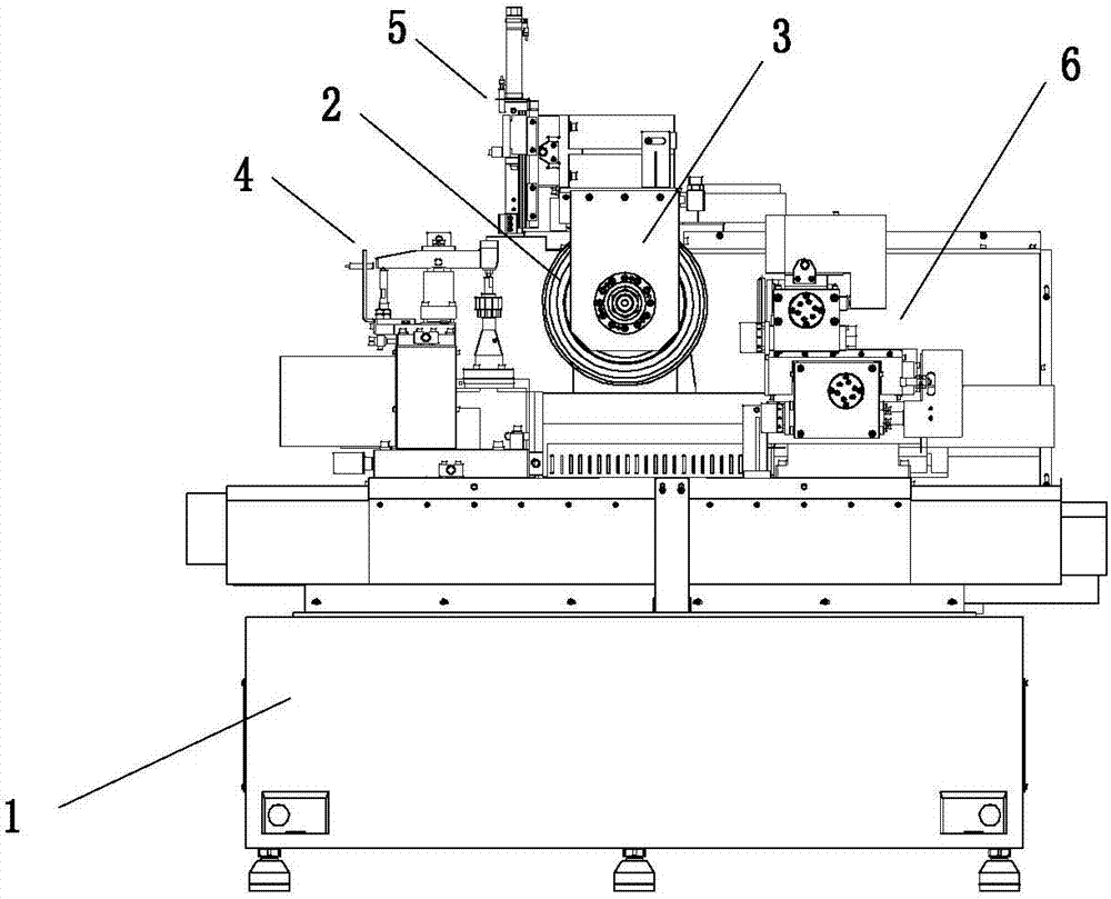
[0027] Such as Figure 1 to Figure 9 As shown, the present invention includes a bed 1, a grinding wheel 2, a workpiece fixture mechanism 4, a workpiece positioning mechanism 5, and a grinding wheel dressing mechanism 6. The grinding wheel 2 is set on the grinding wheel spindle, and the grinding wheel spindle is supported on the grinding wheel box 3 by bearing support. The grinding wheel box 3 is fixedly installed on the bed 1, the workpiece fixture mechanism 4 and the grinding wheel dressing mechanism 6 are respectively arranged on both sides of the grinding wheel box 3, and the workpiece positioning mechanism 5 is installed on the grinding wheel box 3.

[0028] The workpiece fixture mechanism 4 includes a workpiece slide table 41, a pressure bar 45, an index plate 42 and a rotary oil cylinder. The workpiece slide table 41 is installed on the ...


PUM


Abstract

A rotor slot grinding machine comprises a grinding machine body, a grinding wheel, a workpiece fixture mechanism, a workpiece positioning mechanism and a grinding wheel dressing mechanism; the grinding wheel is installed on a grinding wheel spindle in a sleeving mode, the grinding wheel spindle is supported and installed on a grinding wheel box through a bearing, and the grinding wheel box is fixedly installed on the grinding machine body; the workpiece fixture mechanism and the grinding wheel dressing mechanism are arranged on the two sides of the grinding wheel box correspondingly; and the workpiece positioning mechanism is installed on the grinding wheel box. According to the rotor slot grinding machine, clamping and angle dividing of a workpiece can be achieved through the workpiece fixture mechanism, and accordingly, the grinding wheel can accurately grind a rotor slot; and the two end faces and the excircle face of the grinding wheel can be dressed through the grinding wheel dressing mechanism, and thus, the precision of the end faces and the excircle face of the grinding wheel is ensured. The rotor slot grinding machine is reasonable in structural layout, high in machining efficiency and precise in positioning, and the excircle face of a rotor cannot be damaged.

Description

technical field [0001] The invention belongs to the field of grinder equipment, and in particular relates to a rotor groove grinder. Background technique [0002] Such as figure 1 The rotors shown are widely used in products such as vane pumps, automotive steering pumps, and automotive air-conditioning compressor rotors. The key precision of the rotor is the flatness of the two sides of the radial grooves on the outer peripheral surface of the rotor. Therefore, in the rotor processing After forming, it is necessary to grind the groove of the rotor. The existing rotor groove grinding machine grinds the rotor groove through the grinding wheel, and then the existing rotor is difficult to locate during the processing, and the rotor workpiece often appears in the feeding process. The groove cannot correspond to the grinding wheel accurately, and the grinding wheel cannot be inserted into the rotor groove, and the grinding wheel is easy to touch with the peripheral surface of the...

Claims


Application Information

Patent Timeline
Patent Type & Authority Applications(China)
IPC IPC(8): B24B19/02B24B41/06B24B41/02B24B49/00B24B53/06B24B53/075
CPCB24B19/02B24B41/02B24B41/06B24B49/00B24B53/062B24B53/075Y02P70/10
Inventor 陈欢
Owner 绍兴松菱机床有限公司
Learn More