Check patentability & draft patents in minutes with Patsnap Eureka AI!

Method and apparatus for using heat map representation for device implementation of logical CPU division

A technology of heat map and graphic representation, applied to program control devices, input/output processes of data processing, instruments, etc., can solve problems such as difficult monitoring

Active Publication Date: 2016-12-21
MICROSOFT TECH LICENSING LLC
View PDF5 Cites 0 Cited by
  • Summary
  • Abstract
  • Description
  • Claims
  • Application Information

AI Technical Summary

Problems solved by technology

One of the problems with this is that given that a computing device can include a large number of logical CPU partitions, it can be difficult for a user to monitor activity across all logical CPU partitions of the computing device.

Method used


Image

  • Method and apparatus for using heat map representation for device implementation of logical CPU division
  • Method and apparatus for using heat map representation for device implementation of logical CPU division
  • Method and apparatus for using heat map representation for device implementation of logical CPU division

Examples


Embodiment Construction

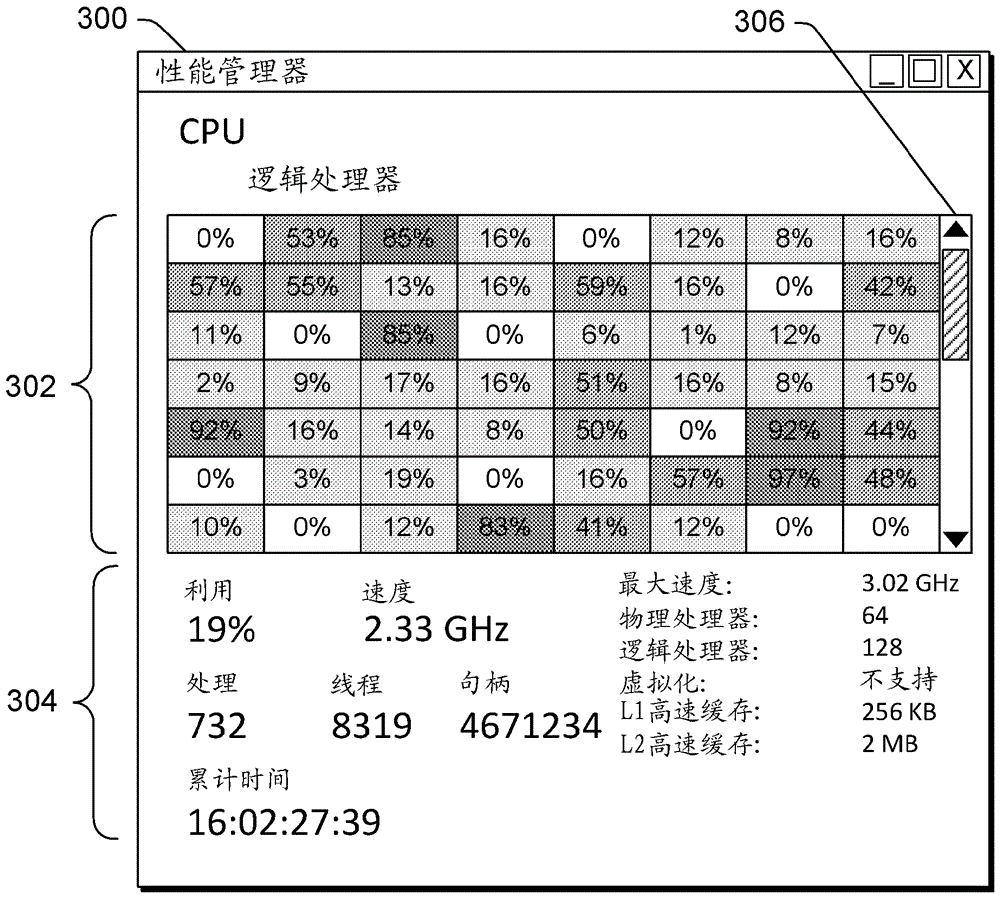
[0016] Here we discuss the use of heat map representation of logical CPU partitions. A computing device includes multiple logical CPU partitions, such as multiple logical processors. The use of these multiple logical CPU partitions can be displayed in various ways. If the computing device includes less than a threshold number of logical CPU partitions, a graphical representation is used wherein a plurality of graphs are displayed and each graph is a graph of usage of a corresponding logical CPU partition over a particular amount of time. However, if the computing device includes at least a threshold number of logical CPU partitions, a heat map representation is used in which a table is displayed with a plurality of cells and each cell displays usage of a corresponding logical CPU partition. Each cell is displayed in one of a number of different ways, such as using different color intensities, based on usage of the corresponding logical CPU partition.

[0017] figure 1 is a ...


PUM


Abstract

Displays the logical central processing unit (CPU) partition management view for devices with multiple logical CPU partitions. The management view is displayed as a heat map representation comprising a plurality of cells, each cell corresponding to one of a plurality of logical CPU partitions. As part of the heat map representation, each of the plurality of cells is displayed in one of a number of different ways based on usage of the corresponding logical CPU partition and identifies usage of a corresponding one of the plurality of logical processors The used value can also be displayed in the cell.

Description

[0001] related application [0002] This application claims priority to US Provisional Application Serial No. 61 / 551886, filed October 26, 2011, by Christina L. Rhodes et al., entitled "Logical Processors Heat Map Representation," the disclosure of which is hereby incorporated by reference in its entirety. Background technique [0003] As technology has advanced, central processing units (CPUs) used in various computing devices have evolved from a single instruction execution core with serial execution of instructions to multiple instruction execution cores with parallel execution of instructions and logical division. These computing devices have also evolved from having a single CPU to having multiple CPUs executing instructions in parallel. While these advances have increased the processing power of computing devices, they are not without their problems. One of the problems with this is that given that a computing device may include a large number of logical CPU partitions,...

Claims


Application Information

Patent Timeline
Patent Type & Authority Patents(China)
IPC IPC(8): G06F9/44G06F3/0488G06F3/0481
Inventor C.L.罗德斯P.S.波诺马雷夫M.P.杜伊南P.D.多纳特
Owner MICROSOFT TECH LICENSING LLC
Features
  • R&D
  • Intellectual Property
  • Life Sciences
  • Materials
  • Tech Scout
  • Unparalleled Data Quality
  • Higher Quality Content
  • 60% Fewer Hallucinations
Learn More