Supercharge Your Innovation With Domain-Expert AI Agents!

Integrally-formed combined pipe fitting manufacturing method

A manufacturing method and technology for pipe fittings, applied in manufacturing tools, welding equipment, metal processing equipment, etc., can solve the problems of limited effect of frame shape fluency, uneven thickness, thickening of pipe wall thickness, etc., and achieve easy expansion and change. , smooth shape, small shape variability effect

Inactive Publication Date: 2013-03-06
野宝车料工业(深圳)有限公司
View PDF8 Cites 5 Cited by
  • Summary
  • Abstract
  • Description
  • Claims
  • Application Information

AI Technical Summary

Problems solved by technology

However, in the method disclosed in this new patent, the welded part 12 is at the overlapping junction 13 of the aforementioned pipe fittings 10. Since the pipe walls of the aforementioned pipe fittings 10 overlap each other and the solder filled in during the welding process, it will be welded after welding. The thickness of the pipe wall becomes thicker, and the junction overlap 13 is the place where the shape variation of the aforementioned pipe fittings 10 is the largest, and it is in a superimposed state or an inner concave structural surface, so in the process of hydroforming, the junction overlap 13 tube wall is prone to uneven thickness during expansion and molding, resulting in low yield
Therefore, using this method, the effect of the smoothness of the shape of the formed frame is still limited, which has a great impact on the yield rate

Method used


Image

  • Integrally-formed combined pipe fitting manufacturing method
  • Integrally-formed combined pipe fitting manufacturing method
  • Integrally-formed combined pipe fitting manufacturing method

Examples


Embodiment Construction

[0030] Below in conjunction with accompanying drawing and embodiment the present invention is described in detail:

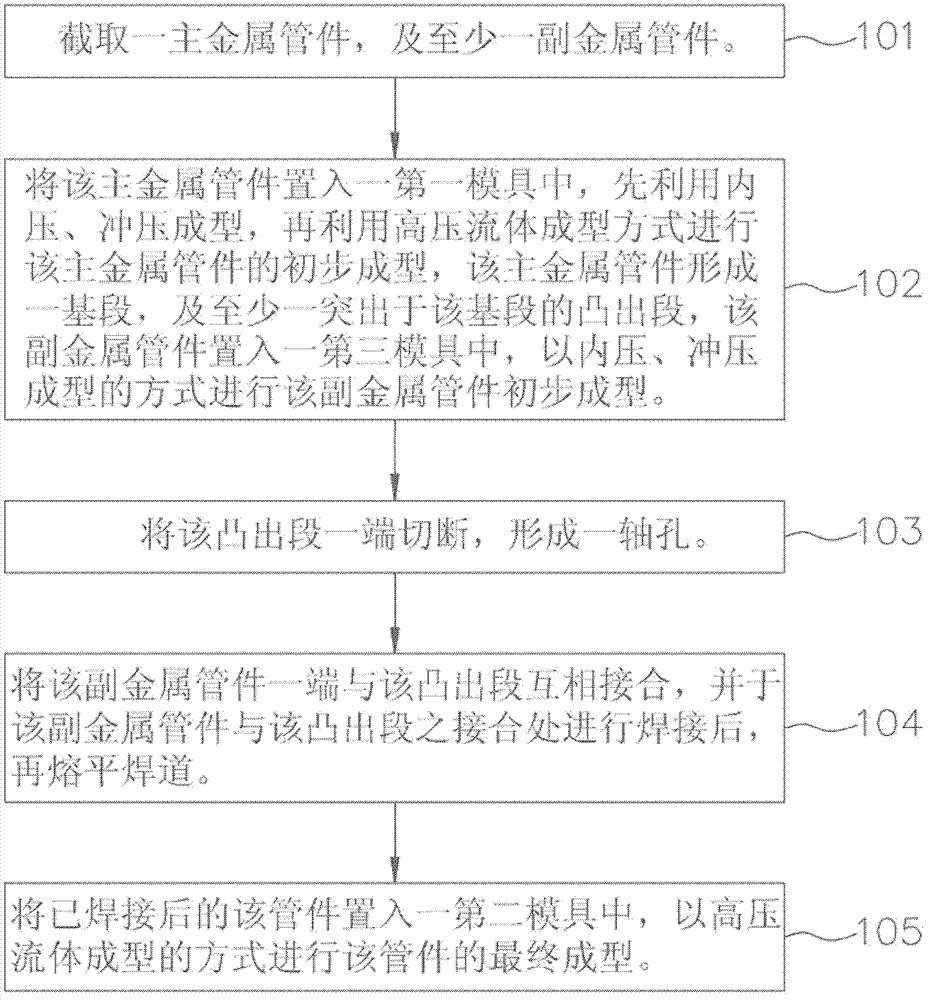
[0031] refer to figure 2 and image 3 , the first preferred embodiment of the manufacturing method of the integrally formed composite pipe fitting of the present invention comprises the following steps:

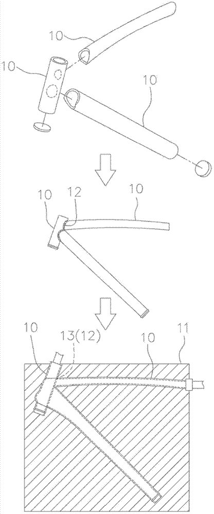
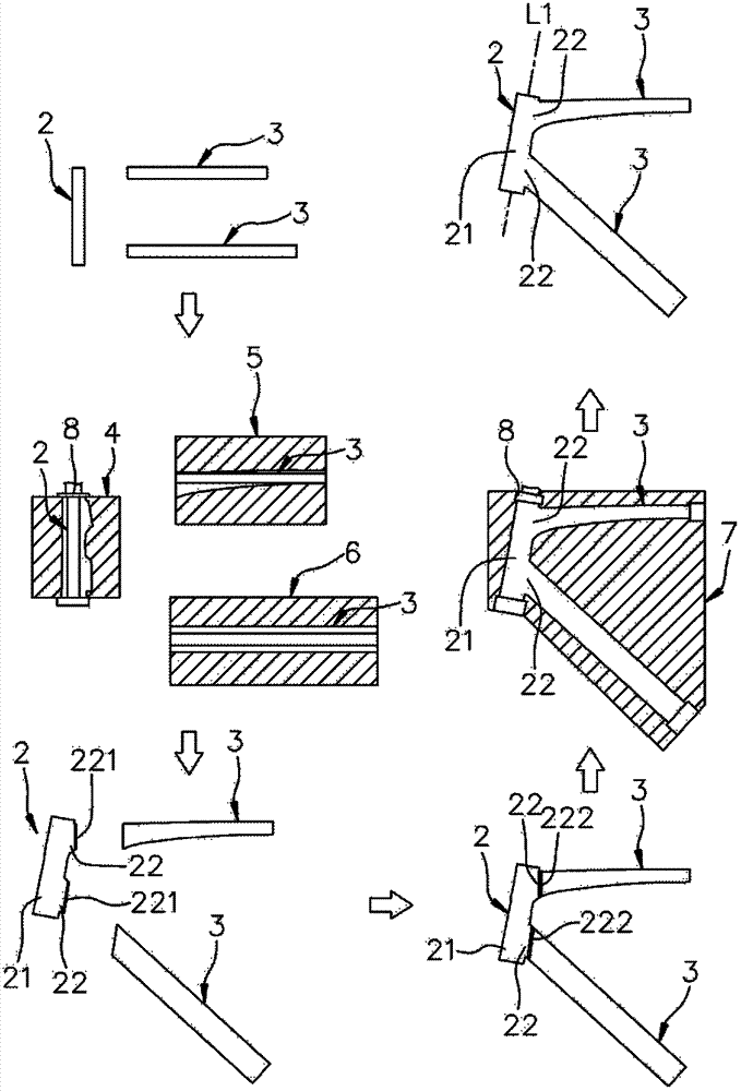
[0032] Step 101: Cutting out one main metal pipe 2 and two auxiliary metal pipes 3 . The material used for the main metal pipe 2 and the aforementioned auxiliary metal pipe 3 is aluminum alloy.

[0033] Step 102: Put the main metal pipe fitting 2 into a first mold 4, first use internal pressure and stamping to form, and then use high-pressure fluid forming to perform preliminary molding of the main metal pipe fitting 2, so that the main metal pipe fitting 2 is formed into a A base section 21, and two protruding sections 22 protruding from the base section 21. The aforementioned auxiliary metal pipe fittings 3 are placed into a third mold 5 and a fourth mol...


PUM


Abstract

An integrally-formed combined pipe fitting manufacturing method includes the steps: (a) cutting out a main metal pipe fitting and at least one auxiliary metal pipe fitting; (b) placing the main metal pipe fitting into a first die, subjecting the main metal pipe fitting to preliminary forming by means of internal pressure and press forming and high-pressure fluid forming to form a base section and at least one protruding section protruding out of the base section on the main metal pipe fitting; (c) combining one ends of the auxiliary metal pipe fittings with the protruding sections, welding the joints of the auxiliary metal pipe fittings with the protruding sections, and flatly melting weld beads; and (d) placing the welded pipe fitting into a second die to subject the pipe fitting to final forming by means of high-pressure fluid forming.

Description

technical field [0001] The invention relates to a manufacturing method of a bicycle pipe fitting, in particular to a manufacturing method of an integrally formed composite pipe fitting. Background technique [0002] With the awakening of people's awareness of leisure life, bicycles are no longer just a simple means of transportation, but also a kind of exercise tool that people use for leisure and fitness. Therefore, people pay more attention to the requirements of bicycles. Whether it is practicality or the shape of the car body, it is an important link that bicycle manufacturers need to carefully consider. [0003] In order to improve the shape of the bicycle and increase the overall appearance, the manufacturing method of the bicycle frame was the earliest welding method. However, with the welding method, the pipe fittings will leave weld bead after welding, which will cause the shape to be unsmooth and affect the appearance. Welding is easy to cause defects and stress c...

Claims


Application Information

Patent Timeline
Patent Type & Authority Applications(China)
IPC IPC(8): B23P15/00B21D26/033B23K31/02
Inventor 林春山
Owner 野宝车料工业(深圳)有限公司
Features
  • R&D
  • Intellectual Property
  • Life Sciences
  • Materials
  • Tech Scout
  • Unparalleled Data Quality
  • Higher Quality Content
  • 60% Fewer Hallucinations
Learn More