Railway locomotive and railway locomotive traction device

A technology for traction devices and railway locomotives, which is applied to railway car body parts, railway couplings, transportation and packaging, etc., can solve the problems of axle load transfer, long rod body, high cost of forging dies, etc., to reduce lateral force, The effect of overcoming axle load transfer and saving manufacturing costs

Inactive Publication Date: 2013-03-06
DATONG ELECTRIC LOCOMOTIVE OF NCR
View PDF9 Cites 7 Cited by
  • Summary
  • Abstract
  • Description
  • Claims
  • Application Information

AI Technical Summary

Problems solved by technology

[0004] The above-mentioned traction device has the following defects: 1. The manufacturing cost is high. The drawbar 3 generally adopts a forged structure. Its center of gravity is far away from the center of rotation of the bogie, that is, the center of gravity of the bogie. When the locomotive is in traction and braking, the inclined rod body has a vertical component force, which will cause the axle load to transfer, and a large lateral force will appear between the wheel and the track.

Method used


Image

  • Railway locomotive and railway locomotive traction device
  • Railway locomotive and railway locomotive traction device
  • Railway locomotive and railway locomotive traction device

Examples


Embodiment Construction

[0023] In order to make the purpose, technical solutions and advantages of the present invention clearer, the technical solutions in the embodiments of the present invention will be clearly and completely described below in conjunction with the accompanying drawings in the embodiments of the present invention. Obviously, the described embodiments are the Some, but not all, embodiments are invented. Based on the embodiments of the present invention, all other embodiments obtained by persons of ordinary skill in the art without creative efforts fall within the protection scope of the present invention.

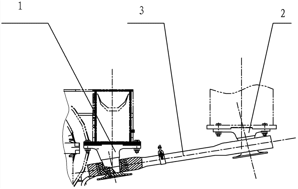
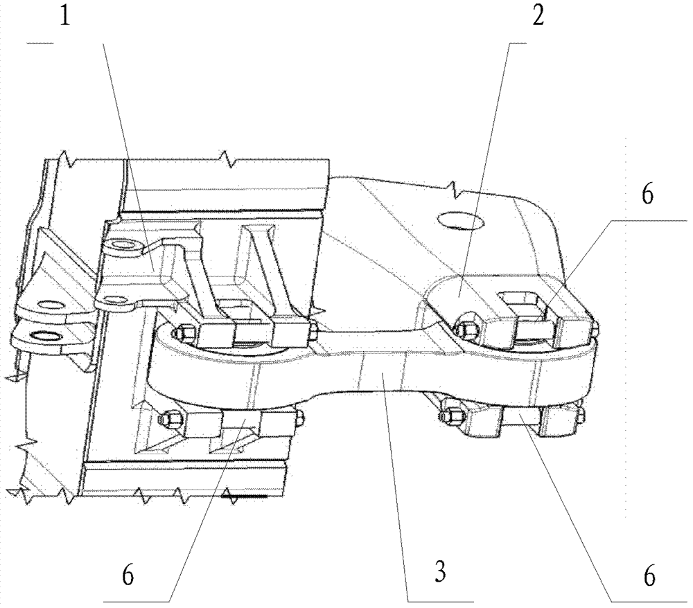
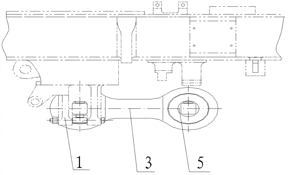
[0024] figure 2 A three-dimensional schematic diagram of the structure of the railway locomotive traction device provided by the embodiment of the present invention, image 3 The front view of the structure of the railway locomotive traction device provided by the embodiment of the present invention, Figure 4 for image 3 According to the top view, the embodiment of the pre...


PUM


Abstract

The invention provides a railway locomotive and a railway locomotive traction device. The traction device comprises a bogie traction seat fixedly mounted on a bogie and a locomotive body traction seat fixedly mounted on a locomotive body, wherein the bogie traction seat is arranged on the upper portion of a lateral end of the bogie and is located on a same horizontal line with the locomotive body traction seat. The traction device further comprises a traction bar which is used for being horizontally arranged between the bogie traction seat and the locomotive body traction seat, two through holes with central lines parallel to each other form at two ends of the traction bar respectively, and the traction bar is used for being fixedly connected with the bogie traction seat and the locomotive body traction seat respectively. Length of the traction bar is designed to be short as far as possible, and accordingly manufacturing cost is saved, the defect that an oblique bar having vertical component force causes axle load transfer in the prior art is overcome and transverse force between wheels and rails is reduced.

Description

technical field [0001] The invention relates to railway locomotive technology, in particular to a railway locomotive traction device and a railway locomotive. Background technique [0002] The railway locomotive traction device is used to connect the locomotive bogie and the locomotive body. It is a device that can transmit force between the bogie and the locomotive body to ensure the uniform distribution of the axle load of the locomotive. When the locomotive is running on the track, The swivel motion of the bogie relative to the car body can be realized. It is both a bearing device and a movable joint. [0003] figure 1 It is a front view of a traction device with a drawbar in the prior art. One end of the installation point of the traction device is located on the bogie fifth wheel far away from the end of the truck head, and the other end is located at the center of the car body or the car body fifth wheel at the front end of the car body. 2, the drawbar 3 is installe...

Claims


Application Information

Patent Timeline
Patent Type & Authority Applications(China)
IPC IPC(8): B61G1/40
Inventor 刘辉李嘉伟石强米立柱张委袖赵清海刘艳林
Owner DATONG ELECTRIC LOCOMOTIVE OF NCR
Why Eureka
Try Eureka