Thermostatic dehumidifying device for air-conditioner

A constant temperature dehumidification and air conditioner technology, which is applied in the field of air conditioning, can solve the problem of low cooling effect, and achieve the effect of precise constant temperature dehumidification that meets the requirements of temperature and humidity

Active Publication Date: 2013-03-06
HAIER GRP CORP +1
View PDF6 Cites 11 Cited by
  • Summary
  • Abstract
  • Description
  • Claims
  • Application Information

AI Technical Summary

Problems solved by technology

It can be seen that when cooling, the heat exchange coil a is not used, resulting in a low cooling effect

Method used


Image

  • Thermostatic dehumidifying device for air-conditioner
  • Thermostatic dehumidifying device for air-conditioner
  • Thermostatic dehumidifying device for air-conditioner

Examples


Embodiment Construction

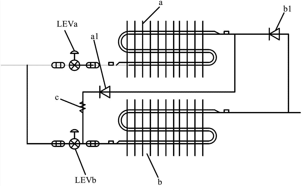
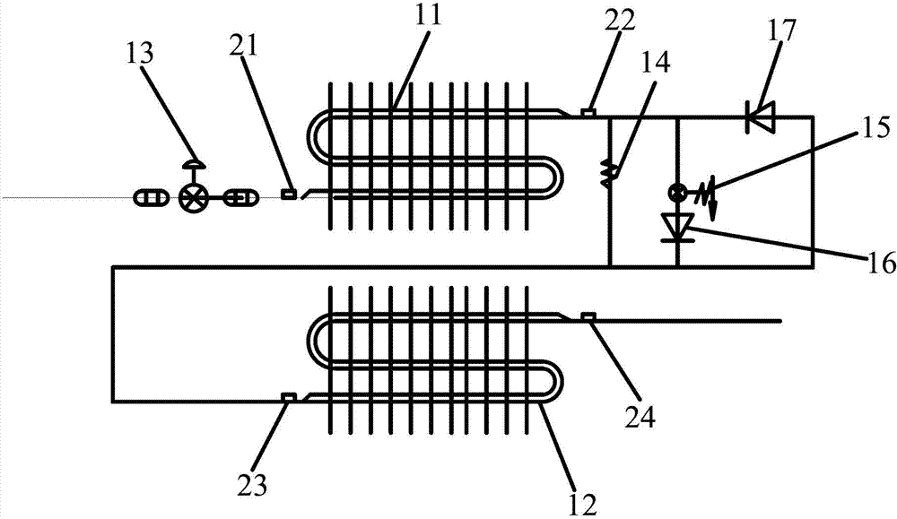
[0036] Embodiments of the present invention will be described in detail below in conjunction with the accompanying drawings. see figure 2 The air conditioner provided by the embodiment of the present invention includes: a first heat exchange coil 11 and a second heat exchange coil 12 arranged up and down in the air conditioner indoor unit casing, and a second heat exchange coil 12 is arranged on the casing below the second heat exchange coil 12 The air port, the air entering from the air inlet passes through the second heat exchange coil 12 and the first heat exchange coil 11 sequentially from bottom to top, and then is blown out from the air outlet on the casing.

[0037] The above two coils can also be arranged horizontally, and the air inlets can also be arranged horizontally, as long as the first heat exchange coil 11 and the second heat exchange coil 12 are located in the air duct and arranged in turn against the wind direction.

[0038] The first heat exchange coil 11 ...


PUM


Abstract

The invention provides a thermostatic dehumidifying device for an air-conditioner. The thermostatic dehumidifying device comprises an electronic expansion valve, a first heat exchange coil pipe, a throttle valve bank and a second heat exchange coil pipe, which are sequentially connected in a refrigerant pipeline in series, and are also sequentially arranged in an air channel of an indoor unit of the air-conditioner in the windward direction. With the electronic expansion valve and the throttle valve bank, in the refrigerating mode of the air-conditioner, a refrigerant enters the first heat exchange coil pipe to refrigerate and then enters the second heat exchange coil pipe to refrigerate again, so that the refrigerating capacity is increased, and the heat exchange efficiency of the air-conditioner is improved. In the dehumidification mode, air firstly passes through the second heat exchange coil pipe to be cooled and dehumidified, the air is heated when passing through the nearby position of the first heat exchange coil pipe, so that the indoor air is heated again after being dehumidified and cooled, the effect of thermostatic dehumidification is realized, and the demands of people on temperature and humidity are met.

Description

technical field [0001] The invention relates to the technical field of air conditioning, in particular to a constant temperature dehumidification device for an air conditioner. Background technique [0002] With the development of technology, air conditioner design is developing towards a smarter and more humane direction. Especially when some coastal cities or areas along the river use existing air conditioners in special seasons, [0003] Due to the relatively high relative humidity of the outdoor air, if the temperature is adjusted to a suitable level, the humidity is often not suitable, and when the humidity is adjusted to a suitable level, the temperature is often not suitable, which greatly affects the comfort of the human body. [0004] For dehumidification schemes currently in use, see figure 1 , including two heat exchange coils: heat exchange coil a in the upper part and heat exchange coil b in the lower part in the figure, two electronic expansion valves: LEVa a...

Claims


Application Information

Patent Timeline
Patent Type & Authority Applications(China)
IPC IPC(8): F24F11/02F24F13/30
Inventor 国德防宋强刘景升郑品迪李银银
Owner HAIER GRP CORP
Why Eureka
Try Eureka