Punching die for terminal box

A punching die and terminal box technology, applied in punching tools, metal processing equipment, manufacturing tools, etc., can solve the problems of reducing production efficiency and product quality, complex structure of terminal box punching die, inability to accurately locate, etc. The effect of improving production efficiency, long service life and reducing labor intensity

Inactive Publication Date: 2013-03-13
DALIAN YILIAN METAL FORMING
View PDF0 Cites 3 Cited by
  • Summary
  • Abstract
  • Description
  • Claims
  • Application Information

AI Technical Summary

Problems solved by technology

[0002] In the prior art, the structure of the terminal box punching die is complicated, the assembly operation is troublesome during use, and it cannot be positioned accurately, so the labor intensity is greatly enhanced, and the production efficiency and product quality are reduced.

Method used


Image

  • Punching die for terminal box
  • Punching die for terminal box

Examples


Embodiment Construction

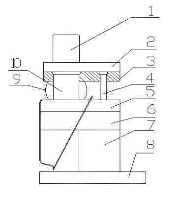
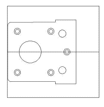
[0010] like figure 1 and figure 2 As shown, the terminal box punching die includes die handle 1, upper template 2, fixed plate 3, guide post 4, die 5, die pad 6, support plate 7, lower die 8 and punch 10, die handle 1 Installed on the upper template 2, the fixed plate 3 is arranged at the lower end of the upper template 2, the guide post 4 and the punch 10 are arranged between the upper template 2 and the die 5, the support plate 7 is installed on the lower template 8, and the die 5 passes through the die The mold pad 6 is installed on the support plate 7, and rubber 9 is provided on both sides of the punch 10. The terminal box punching mold of the present invention has simple and accurate structure assembly, long service life of the mold, simple operation and accurate positioning during use. Advantages, thus reducing labor intensity, improving production efficiency and ensuring product quality.


PUM


Abstract

The invention discloses a punching die for a terminal box. The punching die comprises a die shank, an upper die plate, a fixing plate, a guide column, a concave die, a concave die cushion, a support plate, a lower die plate and a convex die, wherein the die shank is arranged on the upper die plate, the fixing plate is arranged at the lower end of the upper die plate, the guide column and the convex die are arranged between the upper die plate and the concave die, the support plate is arranged on the lower die plate, and the concave die is arranged on the support plate by the concave die cushion. The punching die for the terminal box has the advantages that the structure assembly is simple and precise, and the service life is long; the operation is convenient in the use process, and the positioning is accurate, so the labor strength is reduced, the production efficiency is improved, and the quality is ensured.

Description

technical field [0001] The invention relates to a terminal box punching die. Background technique [0002] In the prior art, the structure of the terminal box punching die is complicated, the assembly operation is troublesome during use, and accurate positioning is not possible, so the labor intensity is greatly enhanced, and the production efficiency and product quality are reduced. Contents of the invention [0003] The purpose of the present invention is to provide a terminal box punching die. [0004] The technical solution adopted by the present invention to achieve the above object is: a terminal box punching die, including a die handle, an upper template, a fixed plate, a guide post, a die, a die pad, a support plate, a lower template and a punch, The mold handle is installed on the upper template, the fixed plate is arranged at the lower end of the upper template, the guide column and the punch are arranged between the upper template and the die, the support plate...

Claims


Application Information

Patent Timeline
Patent Type & Authority Applications(China)
IPC IPC(8): B21D28/34
Inventor 孙冬生范久卫
Owner DALIAN YILIAN METAL FORMING
Why Eureka
Try Eureka