Large-section multi-cabin cast-in-place comprehensive pipe gallery top plate formwork construction system and construction method of large-section multi-cabin cast-in-place comprehensive pipe gallery top plate formwork system

A technology of comprehensive pipe gallery and large section, applied in the field of foundation engineering, can solve the problems of low economic benefit, poor stability, slow construction speed, etc., and achieve the effect of large construction work space, high stability and fast transfer.

Pending Publication Date: 2021-02-19
ANHUI ROAD & BRIDGE GRP
View PDF0 Cites 0 Cited by
  • Summary
  • Abstract
  • Description
  • Claims
  • Application Information

AI Technical Summary

Problems solved by technology

[0005] The purpose of the present invention is to provide a large-section multi-chamber cast-in-place comprehensive pipe gallery roof formwork construction system and construction method, aiming to solve

Method used


Image

  • Large-section multi-cabin cast-in-place comprehensive pipe gallery top plate formwork construction system and construction method of large-section multi-cabin cast-in-place comprehensive pipe gallery top plate formwork system
  • Large-section multi-cabin cast-in-place comprehensive pipe gallery top plate formwork construction system and construction method of large-section multi-cabin cast-in-place comprehensive pipe gallery top plate formwork system
  • Large-section multi-cabin cast-in-place comprehensive pipe gallery top plate formwork construction system and construction method of large-section multi-cabin cast-in-place comprehensive pipe gallery top plate formwork system

Examples


Embodiment Construction

[0041]In order to make the purpose, technical solutions and advantages of the embodiments of the present invention clearer, the technical solutions in the embodiments of the present invention will be clearly and completely described below in conjunction with the embodiments of the present invention. Obviously, the described embodiments are part of the present invention Examples, not all examples. Based on the embodiments of the present invention, all other embodiments obtained by persons of ordinary skill in the art without creative efforts fall within the protection scope of the present invention.

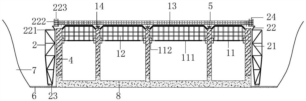
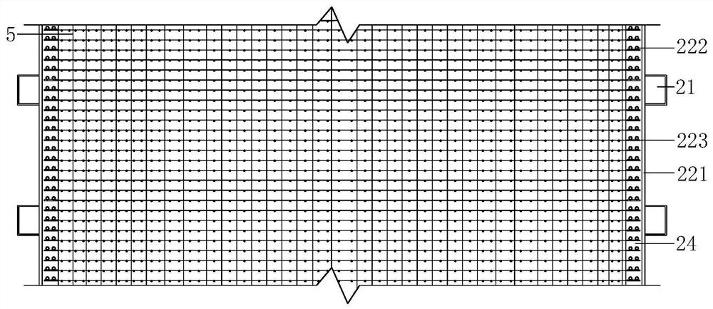
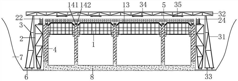
[0042] combined with Figure 1 to Figure 6 , the present invention provides a large-section multi-chamber cast-in-place integrated pipe gallery roof formwork construction system and construction method, aiming to solve the current technology of large-section multi-cabin cast-in-place integrated pipe gallery roof formwork slow construction speed, poor stability and low economic ben...


PUM


Abstract

The invention provides a large-section multi-cabin cast-in-place comprehensive pipe gallery top plate formwork construction system and a construction method of a large-section multi-cabin cast-in-place comprehensive pipe gallery top plate formwork system. The large-section multi-cabin cast-in-place comprehensive pipe gallery top plate formwork construction system mainly comprises a movable top plate construction platform, movable top plate steel bar binding bed jigs, a top plate formwork erecting system and a top plate steel bar cage shaping support; adjustable opposite-jacking supporting rodsare erected on the upper portions of the adjacent pipe gallery side walls, a scaffold is erected on the foundation of the adjustable opposite-jacking supporting rods, and a pipe gallery top plate bottom mold is installed at the tops of the scaffold; the movable top plate steel bar binding bed jigs are symmetrically arranged on the two sides of the comprehensive pipe gallery, pipe gallery top plate steel bar binding construction is conducted through the movable top plate steel bar binding bed jigs, and a pipe gallery top plate steel bar cage is supported on the top face of the pipe gallery side walls through the shaping support; and top plate side molds are installed on the upper portions of the outer walls of the two ends of the pipe gallery outer side wall through opposite-pull screws, and top plate steel bar auxiliary operation and concrete pouring construction are conducted through the movable top plate construction platform. The large-section multi-cabin cast-in-place comprehensive pipe gallery top plate formwork system is easy to install, large in construction operation space, high in efficiency and good in benefit.

Description

technical field [0001] The invention relates to the technical field of foundation engineering, in particular to a construction system and a construction method for a roof formwork of a large-section multi-chamber cast-in-place comprehensive pipe gallery. Background technique [0002] The underground comprehensive pipe corridor is to gather all kinds of pipelines in the municipal infrastructure, such as electricity, communication, water supply, gas, heating, etc., for unified laying, management and maintenance. It not only solves urban traffic problems, but also greatly promotes the maintenance and operation of municipal services, and also has some functions of preventing natural disasters. [0003] At present, based on the analysis of engineering examples at home and abroad, in non-special environments, the main structure of the comprehensive pipe gallery is mainly divided into two types: cast-in-situ method and prefabricated method according to the construction method. The...

Claims


Application Information

Patent Timeline
IPC IPC(8): E02D29/045
CPCE02D29/045E02D2250/0023E02D2300/002E02D2300/0029
Inventor 李文兵刘通侯凯姚启海徐霖姚成诚
Owner ANHUI ROAD & BRIDGE GRP
Why Eureka
Try Eureka