Control circuit for electrical pantographs
A technology for controlling circuits and pantographs, applied to electric vehicles, current collectors, power collectors, etc., can solve the problems of increased cost, difficulty in purchasing spare parts, and difficulty in installation
- Summary
- Abstract
- Description
- Claims
- Application Information
AI Technical Summary
Problems solved by technology
Method used
Image
Examples
Embodiment Construction
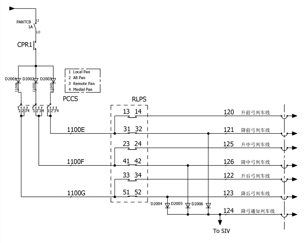
[0017] The electric pantograph control circuit of this embodiment, such as figure 1 As shown, the electric pantograph control circuit is characterized in that it includes: a rising front bow train line 120, a rising middle bow train line 125, a rising rear bow train line 122, a lowering front bow train line 121, a lowering middle bow train line 126, Lowering bow train line 123, lowering bow notification train line 124, wake-up relay COR1, pantograph selection knob switch PCCS with four gears, lifting bow knob switch RLPS, pantograph selection knob switch PCCS has three pairs of input and output Terminals, lifting bow knob switch RLPS has three pairs of normally closed contacts and three pairs of normally open contacts. The three output terminals of the bow selection knob switch PCCS are respectively connected to the front bow control wire 1100E, the middle bow control wire 1100F, and the rear bow control wire 1100G. At points 13 and 14, the forward bow control wire 1100E and ...
PUM
 Abstract
Description
Claims
Application Information
 - R&D
- Intellectual Property
- Life Sciences
- Materials
- Tech Scout
- Unparalleled Data Quality
- Higher Quality Content
- 60% Fewer Hallucinations
Browse by: Latest US Patents, China's latest patents, Technical Efficacy Thesaurus, Application Domain, Technology Topic, Popular Technical Reports.
© 2025 PatSnap. All rights reserved.Legal|Privacy policy|Modern Slavery Act Transparency Statement|Sitemap|About US| Contact US: help@patsnap.com

