
Method for rolling external tube thread, rolling head and rolling equipment thereof

A technology of external thread and rolling head, which is applied in the field of pipe products and pipe processing machinery, and can solve problems that affect the promotion and application of rolling pipe external thread technology, hidden safety hazards of pipe external thread products, and large outer diameter of rolling, etc. Achieve the effect of reducing material cost, reliable and mature process, and reducing contact area

Active Publication Date: 2014-06-18
SHANGHAI PAN CHINA FASTENING SYST
View PDF36 Cites 15 Cited by
  • Summary
  • Abstract
  • Description
  • Claims
  • Application Information

AI Technical Summary

Problems solved by technology

[0006] 2. Due to the huge axial instantaneous stamping or radial extrusion pressure, when the conical surface is formed, the material of the pipe body at the junction of the original outer diameter of the steel pipe and the conical surface, especially the weld seam of the welded pipe, is susceptible to hidden and obvious damage. Sexual damage, resulting in safety hazards for external pipe thread products
[0007] 3. Since the outer diameter of the existing rolling steel pipe blank is the outer diameter of the steel pipe determined by the cutting process, the outer diameter is too large for rolling
However, there are no national and international standards for the outer diameter and wall thickness of rolled steel pipes, and it will take a certain amount of time for market promotion and acceptance, which will inevitably affect the promotion and application of the rolled pipe external thread process.

Method used


Image

  • Method for rolling external tube thread, rolling head and rolling equipment thereof
  • Method for rolling external tube thread, rolling head and rolling equipment thereof
  • Method for rolling external tube thread, rolling head and rolling equipment thereof

Examples


example

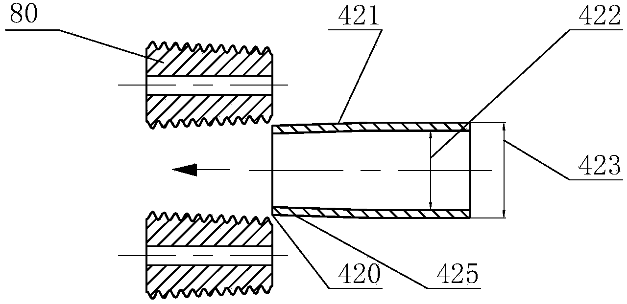
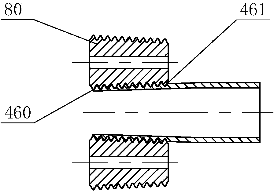
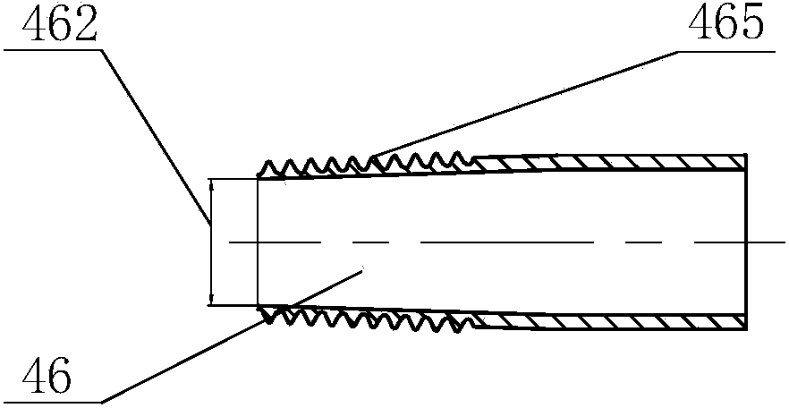
[0181] The following is an example of the on-site installation of a galvanized welded pipe for gas with a specification of DN32, a length of 6000 mm, and a wall thickness of 3.5 mm, which is commonly used in the gas industry. Figure 1 to Figure 6 , Figure 15 to Figure 20 as well as Figure 45 to Figure 46 , compared with the existing rolling processing process for pipe external thread, the aforementioned purpose, technical solution and beneficial effect of the present invention will be further described in detail.

[0182] According to the existing national standard "Welded steel pipe for low-pressure fluid transmission" (GB3091-2008), the outer diameter 423 of the DN32 gas special galvanized steel pipe is 42.4 mm, the ordinary wall thickness is 3.50 mm, and the inner diameter 422 is 35.40 mm. Such as figure 1 As shown, using the existing rolling pipe external thread process, using a large-tonnage axial stamping device, first process the conical surface 425 of 1:16; as f...


PUM


Abstract

The invention provides a method for rolling an external tube thread, a rolling head and rolling equipment thereof. The method includes the steps that a rolling wheel conducts rolling from the thread tail of the thread, and screw thread rolling is completed towards the head portion of the thread. The rolling head comprises at least one rolling wheel which is arranged along the circumference, a corresponding rolling wheel shaft and a rolling wheel seat. The rolling wheel is rotatably fixed on the rolling wheel seat through the rolling wheel shaft, the rolling wheel is provided with a tube thread forming part, and the length of a thread of the tube thread forming part is smaller than the effective thread length of the rolled external tube thread. The rolling head further comprises a radial regulating device which can achieve dynamic rolling and regulate the radial position of the rolling wheel in real time in the whole process, so that the taper required by the rolling technology is formed. The invention further provides the rolling equipment including the rolling head. According to the scheme, the end of a steel tube cannot be deformed easily in the rolling process, hollow cylindrical blank materials are saved obviously, and the rate of finished products is improved.

Description

[0001] This application claims the priority of the earlier application with application number CN201310110406.0 submitted on March 31, 2013. technical field [0002] The invention generally relates to the fields of pipeline products and pipeline processing machinery, and in particular to a method for rolling external threads of pipes, a rolling head and equipment thereof. Background technique [0003] Due to the advantages of high mechanical connection strength and good sealing performance of the pipe thread compared with the cutting pipe external thread, more and more people pay attention to it. The corresponding manufacturing process is listed in the national invention patent "CN200310111695.2" and The invention patent "CN200710106912.7" is also disclosed. However, the two rolling pipe external thread processing methods disclosed in the above two invention patents both perform axial stamping or radial extrusion of the conical surface first and then roll the external pipe t...

Claims


Application Information

Patent Timeline
Patent Type & Authority Applications(China)
IPC IPC(8): B21H3/04
CPCB21H3/044B21H3/04
Inventor 周俊
Owner SHANGHAI PAN CHINA FASTENING SYST
Learn More