Adapter for output shafts of tubular drive devices for winding and unwinding, especially roller blinds, etc., of shading devices

A technology for driving equipment, adapters, applied in the direction of door/window protection devices, windows/doors, building components, etc., can solve problems such as obstructing driving equipment or installation of tubular motors

Inactive Publication Date: 2016-05-25
阿尔佛雷德许内勒贝格公司
View PDF5 Cites 0 Cited by
  • Summary
  • Abstract
  • Description
  • Claims
  • Application Information

AI Technical Summary

Problems solved by technology

However, the above-mentioned increase in the overall length of the drive device or the tubular motor can hinder the installation of the drive device or the tubular motor in the case of relatively narrow roller blinds and the short rollers connected thereto, because the drive device or the tubular motor Motors can no longer be placed in reels

Method used


Image

  • Adapter for output shafts of tubular drive devices for winding and unwinding, especially roller blinds, etc., of shading devices

Examples


Embodiment Construction

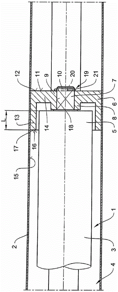
[0012] The tubular drive device 1 partially shown in the drawing for winding and unwinding, in particular roller blinds etc. A motor (not shown) and a transmission mechanism connected thereto (also not shown) are integrated in the housing 3 .

[0013] The housing 3 of the drive device 1 is passed through an adapter or an adapter ring (not shown) with its end 4 directed toward the lateral abutment of the mandrel 2 and with its end facing away from the lateral abutment of the mandrel 2 The end 5 of 4 is non-positively and / or positively connected to the reel 2 via a further adapter 6 . In this case, the roll 2 preferably has an octagonal cross-section. Furthermore, the housing 3 of the drive device 1 is secured against rotation at its end 4 directed toward the lateral bearing of the mandrel 2 by means of a torque bearing (not shown).

[0014] Preferably, the adapter 6 is made of plastic, whereby the manufacture of the adapter 6 is relatively simple and inexpensive.

[0015] At...


PUM


Abstract

The adapter (6) is made of plastic, and is connected to a drive shaft (7) in a force-fit manner for power transmission. A hub (8) is formed, which returns from an end (9) which is averted from a housing (3) of a tubular drive device (1), to a free end (10) of the drive shaft. A side (11) of the hub, which is turned away from the housing, forms an outer side (12) of the adapter.

Description

technical field [0001] The invention relates to an adapter for an output shaft of a tubular drive device for winding and unwinding a blind, in particular a roller blind or the like, wherein the tubular drive consists of a roll capable of being loaded into a roller blind or the like Consists of a housing in a barrel in which the electric motor is integrated with the transmission mechanism connected thereto, wherein the housing is prevented from rotating by a torque bearing mechanism, and wherein the follower of the tubular drive device is An adapter twisted over the output shaft is connected to the reel. Background technique [0002] Such tubular drive devices, or also referred to as tubular motors for short, usually have a relatively large length due to their construction. This is for example because, on the one hand, the drive side has, for example, a motor with several gear trains arranged one behind the other, wherein additionally capacitors for the motor are also requir...

Claims


Application Information

Patent Timeline
Patent Type & Authority Patents(China)
IPC IPC(8): E06B9/72
CPCE06B9/72
Inventor 萨沙·许内勒贝格
Owner 阿尔佛雷德许内勒贝格公司
Why Eureka
Try Eureka