Expansion pipe

An expansion tube and expansion cone technology, which is applied in the field of plugging tools, can solve problems such as low strength of the expansion tube, unsmooth running, and failure, so as to reduce the risk of running into obstruction, reduce production costs, and improve operating efficiency Effect

Active Publication Date: 2013-03-13
PETROCHINA CO LTD
View PDF4 Cites 17 Cited by
  • Summary
  • Abstract
  • Description
  • Claims
  • Application Information

AI Technical Summary

Problems solved by technology

[0004] Due to the conventional expansion pipe tools currently used in China, the expansion cone is a built-in type, that is, the expansion cone is placed in the expansion pipe body before the expansion pipe is expanded, which makes it necessary for the expansion pipe body to accommodate The wide-diameter launch cavity of the expansion cone, the existence of the wide-diameter launch cavity makes the expansion tube prone to the risk of being blocked during the lowering process, resulting in unsmooth or failure of the lowering; in addition, the wide diameter on the expansion tube body The diameter of the launch chamber also makes the overall diameter of the expansion tube body different in thickness, and there are weak links in the tube wall, which easily leads to low overall strength of the expansion tube; moreover, most of the expansion cones currently used in China are monolithic structures, which cannot Realize variable-diameter expansion, and then cannot achieve single-diameter expansion, and cannot achieve the purpose of plugging open-hole formations without loss of borehole size

Method used


Image

  • Expansion pipe
  • Expansion pipe
  • Expansion pipe

Examples


Embodiment Construction

[0041] The following will clearly and completely describe the technical solutions in the embodiments of the present invention with reference to the accompanying drawings in the embodiments of the present invention. Obviously, the described embodiments are only some, not all, embodiments of the present invention. Based on the embodiments of the present invention, all other embodiments obtained by persons of ordinary skill in the art without creative efforts fall within the protection scope of the present invention.

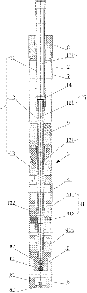
[0042] Such as figure 1 As shown, the present invention provides an expansion tube, which includes a pressing column 1 , an expansion tube body 2 , a combined variable diameter expansion cone 3 , a hydraulic cylinder 4 and a bottom plug 5 . Wherein: the pressing string 1 has an oil pipe 11, a connecting pipe 12 and a central pipe 13 connected in sequence; the expansion pipe body 2 is sleeved outside the oil pipe 11; the combined reducing cone 3 is located at the lo...


PUM


Abstract

The invention discloses an expansion pipe which comprises a pressure pipe column, an expansion pipe body, a combined reducing expansion cone, a hydraulic cylinder and a bull nose, wherein the pressure pipe column is provided with an oil pipe, a connecting pipe and a center pipe which are sequentially connected; the oil pipe is sleeved with the expansion pipe body; the combined reducing expansion cone is positioned at the lower end of the expansion pipe body; the center pipe is sleeved with the combined reducing expansion cone; the hydraulic cylinder is positioned at the lower end of the combined reducing expansion cone; a plurality of pressurizing devices which are connected in series are arranged in the hydraulic cylinder; the lower ends of the pressurizing devices are connected with a ball valve seat; and the bull nose is connected to the lower end of the hydraulic cylinder. According to the expansion pipe disclosed by the invention, the combined reducing expansion cone is arranged outside the expansion pipe body of the expansion pipe, so that the diameter of the pipe column is minimized in the process that the pipe column extends into a barefoot well, and the risk that the pipe column is blocked in the extending process is reduced; and moreover, the reducing expansion can be implemented by the combined reducing expansion cone, the expansion ratio of the expansion pipe can be maximized, the expansion pipe blocks off a layer section of a troublesome stratum of the barefoot well after being expanded, and the effect of no loss of the size of a borehole can be implemented.

Description

technical field [0001] The invention relates to a plugging tool, in particular to an expansion tube with equal diameters, multi-stage pressurization, and two-stage combined diameter reduction for open-hole wells in the petroleum industry. Background technique [0002] As the oil is extracted to the middle and late stages of the oil field, oil wells often suffer from damage problems during the production process. These problems are seriously affecting the normal oil extraction work. Therefore, it is imminent to research and promote new and effective workover technology. Proposed to solve this series of problems played a certain role. At present, the expansion pipe has been successfully applied in the ocean, saving a lot of raw materials. Utilizing expansion tube technology to complete wells can greatly increase oil well production and reduce drilling and completion costs. In addition, the expansion tube technology can also be applied to oil recovery, workover and other oper...

Claims


Application Information

Patent Timeline
Patent Type & Authority Applications(China)
IPC IPC(8): E21B33/122
Inventor 李益良李涛孙强韩伟业陈强明尔扬毕秀玲
Owner PETROCHINA CO LTD
Why Eureka
Try Eureka