
Movable cantilever structure of magnetic suspension train

A technology for maglev trains and activities, applied in electric vehicles, vehicle parts, electric traction, etc., can solve the problems of many mechanical failure factors, high line requirements, and high investment costs, and achieve simplified complexity and technical difficulty, simple technology, Facilitate the effect of engineering

Inactive Publication Date: 2013-03-20
CRRC NANJING PUZHEN CO LTD
View PDF6 Cites 5 Cited by
  • Summary
  • Abstract
  • Description
  • Claims
  • Application Information

AI Technical Summary

Problems solved by technology

[0003] At present, in the suspension frame of maglev vehicles at home and abroad, in order to solve the problem of passing through the curves and ramps of the line, complex mechanical decoupling structures and complex shock absorption and damping system devices are used. The technology is complex and there are many mechanical failure factors.
High requirements on lines and high investment costs

Method used


Image

  • Movable cantilever structure of magnetic suspension train
  • Movable cantilever structure of magnetic suspension train

Examples


Embodiment Construction

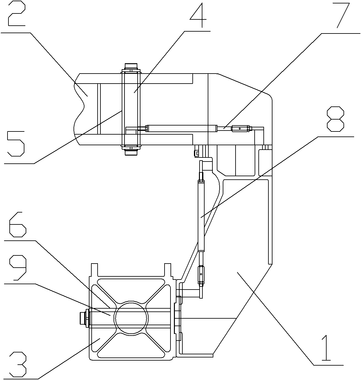
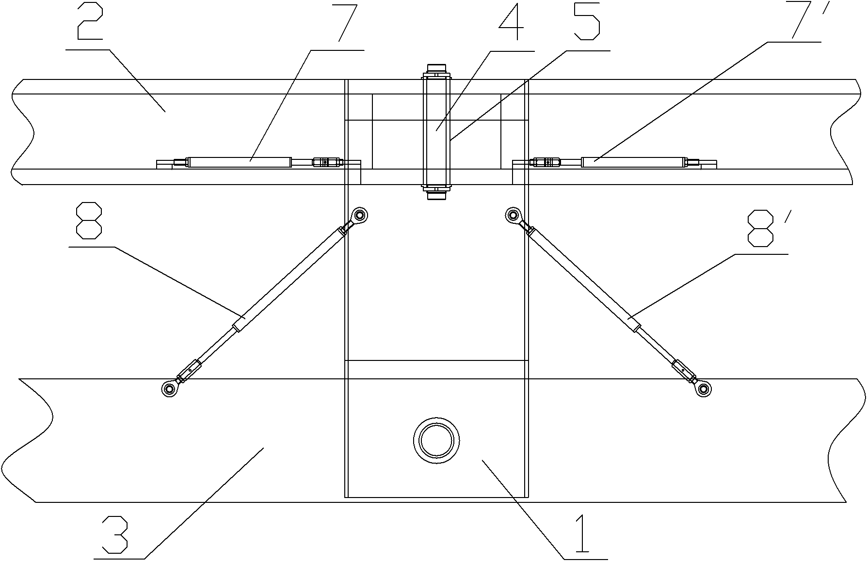
[0013] Such as figure 1 , figure 2 As shown, the movable cantilever structure of the maglev train of the present embodiment includes a C-shaped cantilever bracket 1, the upper part of the C-shaped cantilever bracket 1 is rotationally connected with the suspension frame frame 2 through the vertical rotating shaft 4, and the lower part is installed with the electromagnet through the horizontal rotating shaft 9. The arm 3 is rotatably connected, the horizontal shaft 9 is perpendicular to the electromagnet installation arm 3, and a pair of transverse damping shock absorbers 7 (7') and a pair of longitudinal damping shock absorbers 8 (8') are arranged on both sides of the C-shaped cantilever support 1. The two ends of the transverse damping shock absorber 7 (7') are respectively connected to the C-shaped cantilever bracket 1 and the suspension frame frame 2, and the two ends of the longitudinal damping shock absorber 8 (8') are respectively connected to the C-shaped cantilever bra...


PUM


Abstract

A movable cantilever structure of a magnetic suspension train comprises a C-type cantilever support. The upper portion of the cantilever is rotationally connected with a suspension support frame through a vertical rotating shaft. The lower portion of the cantilever is rotationally connected with an electromagnet installing arm through a horizontal rotating shaft. The horizontal rotating shaft is perpendicular to the electromagnet installing arm. The two sides of the C-type cantilever support are provided with a pair of transverse dampers and a pair of longitudinal dampers. The two ends of each transverse damper are respectively connected with the C-type cantilever support and the suspension support frame. The two ends of each longitudinal damper are respectively connected with the C-type cantilever support and the electromagnet installing arm. The movable cantilever structure of the magnetic suspension train enables single-cantilever control to be achieved and greatly simplifies the complexity and the technical difficulty of the mechanical decoupling of a suspension support of the prior magnetic suspension vehicle. The parameter matching of dampers arranged on drawbars are simplified and singularized. The ramp through capacity and the curve passage capacity of the suspension support are improved. The flexibility, the reliability and the safety are improved. The movable cantilever structure of the magnetic suspension train is significant in promoting the engineering of magnetic suspension technology and rapidly achieving the commercialization of magnetic suspension vehicles.

Description

technical field [0001] The invention relates to a movable cantilever structure of a maglev train, which belongs to the field of vehicle body structure design. Background technique [0002] With the rapid development of rail transit, the urbanization process is advancing rapidly, but it also leaves a safety hazard for rail transit. With the occurrence of a particularly serious railway traffic accident on the 7.23 Yongwen Line, people have unprecedented expectations for safer, more environmentally friendly, more energy-saving, and more convenient maglev transportation. [0003] At present, in the suspension frame of domestic and foreign maglev vehicles, in order to solve the problem of passing through the curves and ramps of the line, complex mechanical decoupling structures and complex shock absorption and damping system devices are used. The technology is complex and there are many mechanical failure factors. High requirements on lines and high input costs. Contents of th...

Claims


Application Information

Patent Timeline
Patent Type & Authority Applications(China)
IPC IPC(8): B60L13/04
Inventor 黄中荣
Owner CRRC NANJING PUZHEN CO LTD
Learn More