
desktop vacuum cleaner

A technology for vacuum cleaners and suction ports, which is applied in the directions of vacuum cleaners, suction nozzles, cleaning equipment, etc., can solve the problem of not considering movable suction ports, etc., and achieve the effect of optimizing the suction characteristics

Inactive Publication Date: 2017-04-12
威赛有限公司
View PDF2 Cites 0 Cited by
  • Summary
  • Abstract
  • Description
  • Claims
  • Application Information

AI Technical Summary

Problems solved by technology

Movable suction nozzles adapted to the surface to be vacuumed have not been considered in such devices until now

Method used


Image

  • desktop vacuum cleaner
  • desktop vacuum cleaner

Examples


Embodiment Construction

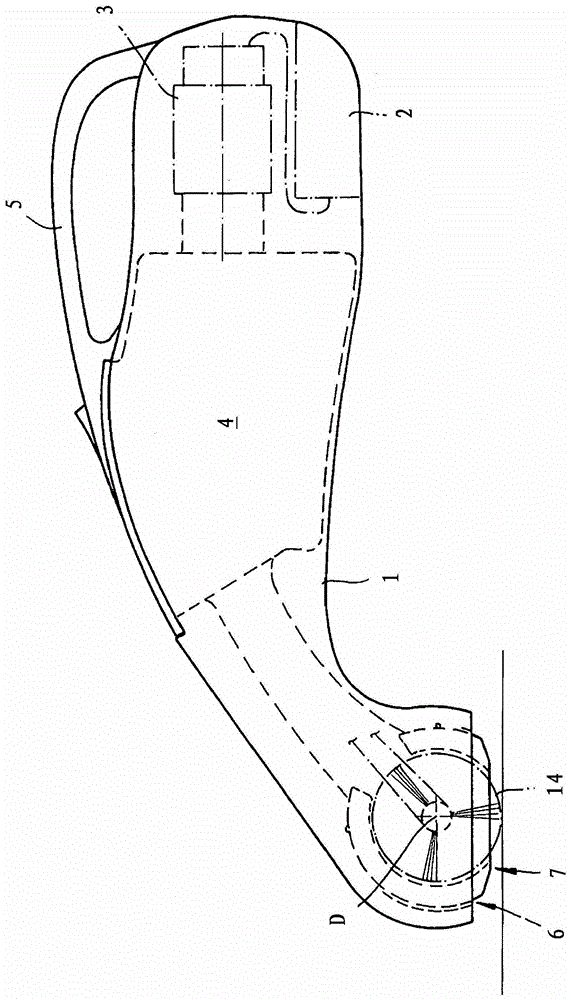
[0014] exist figure 1 The desktop vacuum cleaner shown in has a housing 1 which accommodates an electrically driven extractor 3 and a dust separation device 4 . The housing 1 has a handle 5 and an opening 6, in which a suction mouthpiece 7 mounted so as to be pivotable about an axis of rotation D is arranged and has a front edge 9 and a rear edge 9 in the suction direction. The edge 9' and the inlet surface 10 for suction delimited by the two suction opening edges 8, 8'. A storage battery 2 is provided to supply power to the air extractor. However, it is also within the scope of the invention to connect the device to an external power supply and to provide, alternatively or additionally, a connection socket or a mains connection for the cable.

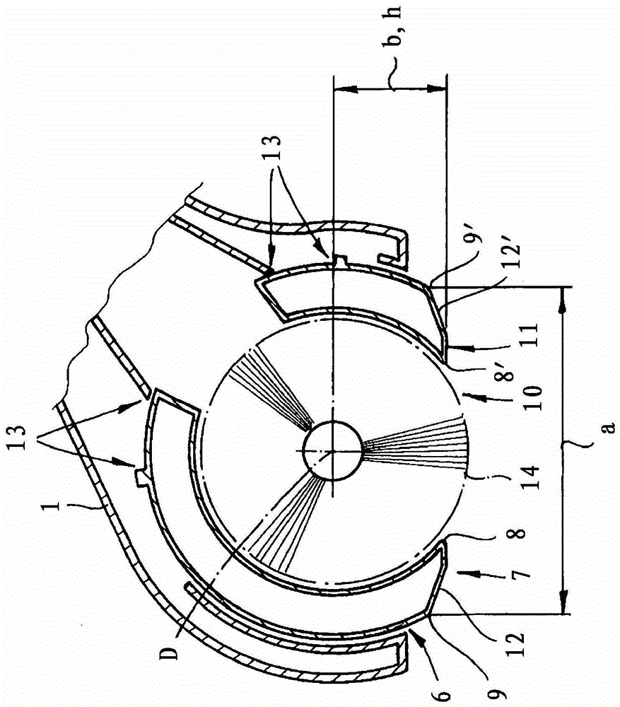
[0015] exist figure 2 In the case of the suction mouthpiece 7 shown in , the distance a between the front edge 9 and the rear edge 9 ′ is greater than the distance b from the inlet surface 10 to the axis of rotation D to be determi...


PUM


Abstract

The device has a suction mouthpiece (7) arranged in an opening (6) of a housing (1), and tiltingly movably mounted around a rotational axis (D). The mouthpiece includes a front edge (9), a rear edge (9') and an entry surface (10) for suction air in a suction direction. The mouthpiece includes a bottom sliding base (11) with two bent or rounded surfaces (12, 12') before and behind the entry surface. A distance (a) between the front and rear edges is larger than a distance (b) between the entry surface and the rotational axis of the mouthpiece.

Description

technical field [0001] The invention relates to a desktop vacuum cleaner, which has a housing that accommodates an electrically driven air extractor and a dust separation device, the housing has a handle and an opening in which a movable A suction mouthpiece mounted in a pivotable manner, which has a front edge and a rear edge in the suction direction and an inlet surface for suction delimited by two suction mouth edges. The tabletop vacuum cleaner constitutes a compact device that can be easily handled by hand and is used for vacuuming tabletops. In addition, the device can also be used to vacuum up cushions and furniture surfaces. Background technique [0002] From US Pat. No. 4,573,237 a tabletop vacuum cleaner is known which has an inclined suction nozzle for taking in dirt-laden air. The tilting suction nozzle can be fixed in two positions by means of locking devices, namely a raised position and a tilted position. The raised position is equivalent to the rigid sucti...

Claims


Application Information

Patent Timeline
Patent Type & Authority Patents(China)
IPC IPC(8): A47L5/26
CPCA47L5/26A47L9/02
Inventor K-D·里尔H·迪尔格D·卡芬伯格
Owner 威赛有限公司
Learn More