Black-flow preventer valve in pipeline

An anti-backflow and valve technology, applied in the direction of valves, etc., can solve the problems of affecting the thickness of the pipeline, no anti-backflow, and insufficient smooth flow of liquid or gas, and achieve the effect of simple structure

Inactive Publication Date: 2013-03-27
于秀月 +2
View PDF11 Cites 17 Cited by
  • Summary
  • Abstract
  • Description
  • Claims
  • Application Information

AI Technical Summary

Problems solved by technology

Its disadvantages are: 1. The structure is more complicated; 2. It is only suitable for hard pipes, and the application is not wide enough; 3. It is necessary to overcome the gravity of the anti-reflux flap when flowing downstream; 4. It affects the thickness of the pipe; 5. It is difficult to install and cannot be placed at will. ; 6. Affect the load bearing of the pipeline and cannot be placed in multiple places
[0006] The disadvantages of the above example: 1. The structure is still relatively complicated; 2. The structure of the medical check valve must overcome the resistance of the stainless steel spring when the liquid or gas flows downstream, which hinders the smooth flow of the pipeline; 3. The medical check valve is The structure of a section of the pipeline cannot be placed randomly; 4. It affects the thickness of the pipeline so that the flow of liquid or gas is not smooth enough; 5. It cannot be placed in multiple places; 6. It cannot prevent the gas or airflow in the pipeline from rising
The disadvantages are: 1. The structure is more complicated; 2. The valve cannot be placed at will; 3. The anti-reflux depends on the elasticity of the valve itself, which makes the anti-reflux effect inaccurate; 4. If the liquid contains impurities, the impurities will be caught between the valves, which is convenient No anti-backflow effect

Method used


Image

  • Black-flow preventer valve in pipeline
  • Black-flow preventer valve in pipeline
  • Black-flow preventer valve in pipeline

Examples


Embodiment Construction

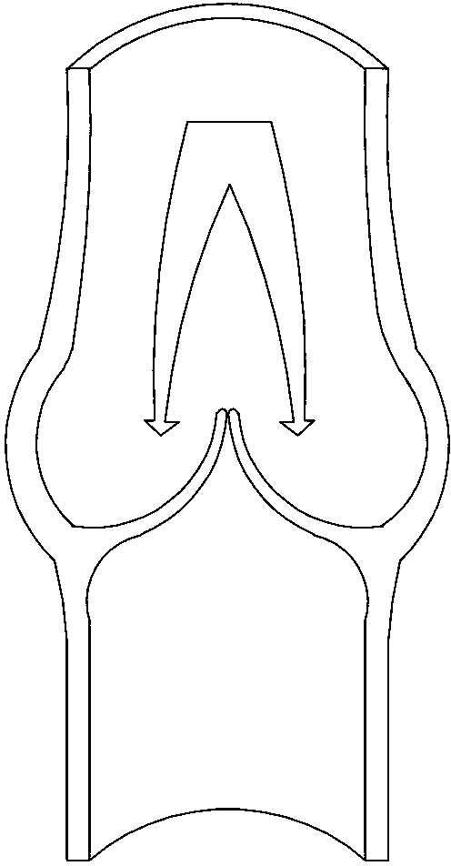
[0035] Such as Figure 6 As shown, the present invention sets two half-moon-shaped thin valves in the lumen just like the human vein valve, facing each other. The width in the middle of the valve is greater than the radius of the lumen, which is 1.5-2.5 times the radius of the lumen where it is located. The root of the valve is slightly Thick (convex sides) arcuate or semicircular ( Figure 6 ) is connected to the inner wall of the lumen to form a bag shape, and the two sides are connected to the opposite valve. Its free edge (concave edge) faces the flow direction to prevent the backflow of liquid or gas. elasticity and toughness. The lumen is transparent, and the two valves are set in eye-catching colors, which is easy to observe. It can be applied to various soft and hard pipes and various parts of the pipe. It has more advantages in medical applications. It can be used in infusion tubes, head, chest, abdomen and limbs. Various drainage tubes, inflatable masks, tracheal t...


PUM


Abstract

The invention discloses a back-flow preventer valve in a pipeline. The back-flow preventer valve in the pipeline comprises a pipe body and valves, wherein the valves are arranged in a pipe cavity. Two valves are designed in the pipe cavity, the width of the middle parts of the valves is greater than the radius of the pipe cavity, and is 1.5-2.5 times the radius of the pipe cavity; the root parts of the valves are thicker than other parts, are arc-shaped and connected with the inner wall of the pipe cavity; free edges of the upper valve and the lower valve face towards the flow direction of the fluid; the valves are light films with elasticity and toughness; and the pipe body is transparent, and the two valves are provided with different colors. The back-flow preventer valve in the pipeline has the advantages that: 1, the two valves are simple and practical, satisfy biomechanics, and can be arranged at a plurality of positions in the same pipe body; 2, down-flow is not affected when the back-flow is prevented; 3, convection of liquid and gas in a drainage pipeline is prevented; and 4, the structure of the pipeline is not affected when the back-flow preventer valve is widely applied to any part of various pipe cavities and pipelines in medical science or non-medical life.

Description

technical field [0001] The invention relates to a technique for preventing reflux in a pipeline, in particular to a valve for preventing reflux in a pipeline used in medical treatment. Background technique [0002] The opening and closing parts are opened or closed by the medium flow and force to prevent the medium from flowing backward. The valve is called a check valve. The check valve is also called a one-way valve or a check valve. On the pipeline that flows downward, the medium is only allowed to flow in one direction to prevent accidents. According to the structure, the check valve can be divided into three types: lift check valve, swing check valve and butterfly check valve. Its disadvantages are: 1. The structure is more complicated; 2. It is only suitable for hard pipes, and the application is not wide enough; 3. It is necessary to overcome the gravity of the anti-reflux flap when flowing downstream; 4. It affects the thickness of the pipe; 5. It is difficult to in...

Claims


Application Information

Patent Timeline
Patent Type & Authority Applications(China)
IPC IPC(8): A61M39/24
Inventor 于秀月刘传玲
Owner 于秀月
Why Eureka
Try Eureka