
Rigid-connection node of combined steel-pipe concrete column and steel beam

A steel tube concrete column, combined technology, applied in the direction of construction, building structure, etc., can solve problems such as engineering hidden dangers, difficulty in making inner partitions, affecting concrete pouring and strength in tubes, etc., to achieve direct force transmission of nodes and construction convenient effect

Active Publication Date: 2014-09-24
金天德 +2
View PDF8 Cites 0 Cited by
  • Summary
  • Abstract
  • Description
  • Claims
  • Application Information

AI Technical Summary

Problems solved by technology

The main disadvantage of this method is that it is difficult to make the inner partition, and it affects the pouring and strength of the concrete in the pipe, which brings hidden dangers to the project

Method used


Image

  • Rigid-connection node of combined steel-pipe concrete column and steel beam
  • Rigid-connection node of combined steel-pipe concrete column and steel beam
  • Rigid-connection node of combined steel-pipe concrete column and steel beam

Examples


Embodiment 1

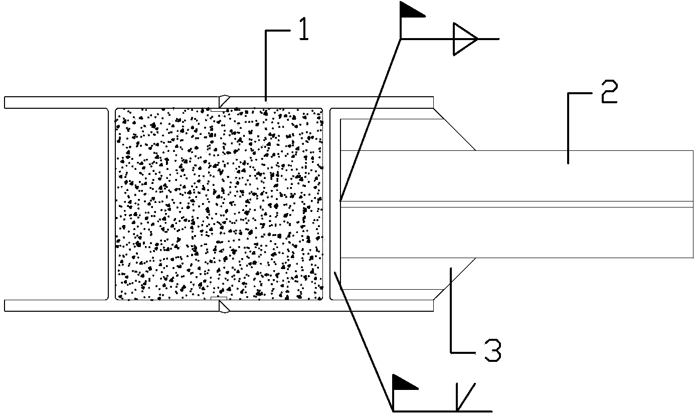
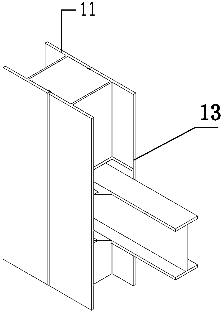
[0026] Refer to attached Figure 1-2 , a rigid connection joint between a composite steel pipe concrete column and a steel beam, including a composite steel pipe concrete column 1 and a steel beam 2, the composite steel pipe concrete column includes two "H" shaped steel 11, the two The two section steels are vertically arranged and welded together through the flange; the web of the section steel is provided with shear studs along the height direction, and concrete 1 is poured in the cavity surrounded by the splicing of the two section steels, and the concrete and the section steel are passed through the The above-mentioned shear studs are connected together; the combined concrete-filled steel tube column is provided with vertically arranged side plates, the steel beam is arranged between the two side plates, and the flanges of the adjacent combined steel-filled steel tube concrete column ends of the steel beam face upward There is a horizontal connecting plate 3 extending in t...

Embodiment 2

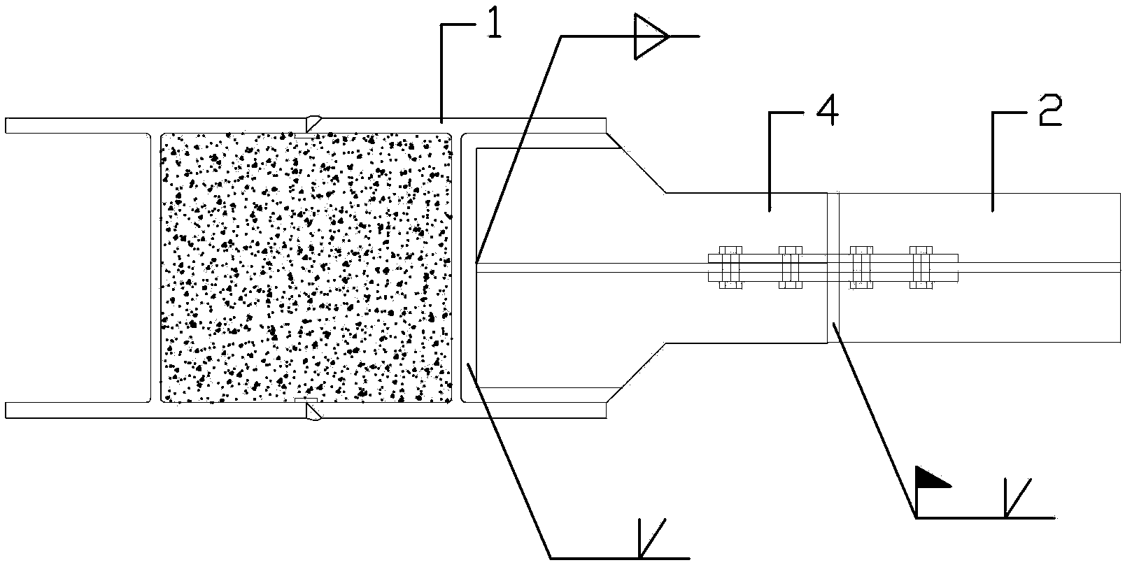
[0028] Refer to attached Figure 3-4 , a rigid connection joint between a composite steel pipe concrete column and a steel beam, including a composite steel pipe concrete column 1 and a steel beam 2, the composite steel pipe concrete column includes two "H" shaped steel, the two The shaped steel is vertically arranged and welded together through the flange; the web of the shaped steel is provided with shear studs along the height direction, and concrete is poured into the cavity formed by the splicing of the two shaped steels, and the concrete and shaped steel pass through the anti- The shear studs are connected into one; the combined concrete-filled steel pipe column is provided with a vertically arranged side plate, and the steel beam is connected to a corbel 4 close to the end of the combined steel-filled concrete column, and the corbel is adjacent to the combined-type concrete-filled steel tube A horizontal connecting plate extends from the flange of the column end toward ...

Embodiment 3

[0030] Refer to attached Figure 5-6 , the steel beams are arranged on one side of the two steel flanges, and the side plate 5 is welded to the steel flanges. The steel beam is welded H-shaped steel. The welds between the flanges of the steel beams and the horizontal connecting plates and the composite steel pipe concrete columns and their side plates are connected by fillet welds, and the others are the same as in the first embodiment.


PUM


Abstract

A rigid connection joint between a composite steel pipe concrete column and a steel beam, including a composite steel pipe concrete column and a steel beam, the composite steel pipe concrete column includes two "H" shaped steels, and the two steel pipes are vertically arranged , welded together through the flange; the web of the section steel is provided with shear studs along the height direction, and concrete is poured in the cavity formed by the splicing of the two section steels, and the concrete and section steel pass through the shear studs connected into one; the combined concrete-filled steel tube column is provided with vertically arranged side plates, and the steel beam is arranged between the two side plates; The connecting plate, the steel beam is welded to the side plate through the horizontal connecting plate; the web plate of the steel beam is welded to the composite steel pipe concrete column with double-sided fillet welds. The node of the invention realizes the "design criterion of strong node and weak member" because the steel beam increases the width of the flange through the horizontal connecting plate in the node area.

Description

technical field [0001] The invention belongs to the technical field of building structure engineering, and in particular relates to a rigid connection node of a composite steel pipe concrete column and a steel beam. Background technique [0002] At present, the connection of steel beams and steel columns, especially steel tube concrete columns, often adopts the method of internal partitions. The internal force of the steel beam is transmitted to the CFST through the internal diaphragm of the column. The main disadvantage of this method is that it is difficult to manufacture the inner partition, and it affects the pouring and strength of the concrete in the pipe, which brings hidden dangers to the project. Contents of the invention [0003] In order to overcome the deficiencies of the prior art, the invention provides a rigid connection joint between a composite steel pipe concrete column and a steel beam. This joint adopts the method that the steel beam flange transmits ...

Claims


Application Information

Patent Timeline
Patent Type & Authority Patents(China)
IPC IPC(8): E04B1/58
Inventor 金天德童根树叶再利
Owner 金天德
Learn More