A kind of integral underground wall construction method

A construction method and integrated technology, applied in sheet pile walls, infrastructure engineering, construction, etc., can solve the problems of reduced wall quality, reduced gripping force, mud pollution, etc., to improve engineering safety and reduce material costs. , the effect of safety in the construction process

Active Publication Date: 2019-09-24
章胜南 +2
View PDF6 Cites 0 Cited by
  • Summary
  • Abstract
  • Description
  • Claims
  • Application Information

AI Technical Summary

Problems solved by technology

[0004] Now there is another construction method is the cast-in-place underground continuous wall. First, use a slotting machine to make a groove in the ground, and then put a reinforcement cage in the mud, insert a pouring pipe into the mud, and pour it at the bottom of the groove through high pressure. The pouring pipe is moved up after each pouring until the entire wall is poured. The wall made by this construction method is not only used as a temporary support structure for the foundation pit, but also as a permanent outer wall of the basement, which greatly reduces the engineering cost. cost, but the construction method of the underground diaphragm wall also has many disadvantages: (1) the requirement for mud is high, the mud treatment cost is high and the mud is easy to cause pollution; (2) the quality of the wall concrete is uneven and unstable, and the size of the wall itself, It is difficult to control the plane shape and vertical position, and there is leakage at the joint of the wall width; (3) Because of the underwater pouring, after the steel cage is placed in the mud, the steel bars are covered with mud, the grip force is reduced, and the quality of the wall will be reduced. If it is lowered, it is easy to cause irregular water seepage on the wall, and the wall is rough, and the steel bars in some places are directly exposed, and there will be mud inclusions, so it is necessary to set up a waterproof lining wall; (4) It is difficult to accurately locate the embedded parts, and the underground continuous wall Can only be used as part of the main structure wall

Method used


Image

  • A kind of integral underground wall construction method
  • A kind of integral underground wall construction method
  • A kind of integral underground wall construction method

Examples


Embodiment Construction

[0039] The present invention will be further described below in conjunction with accompanying drawing and specific embodiment:

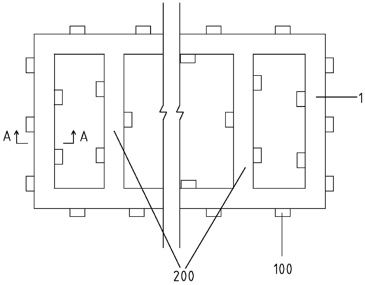
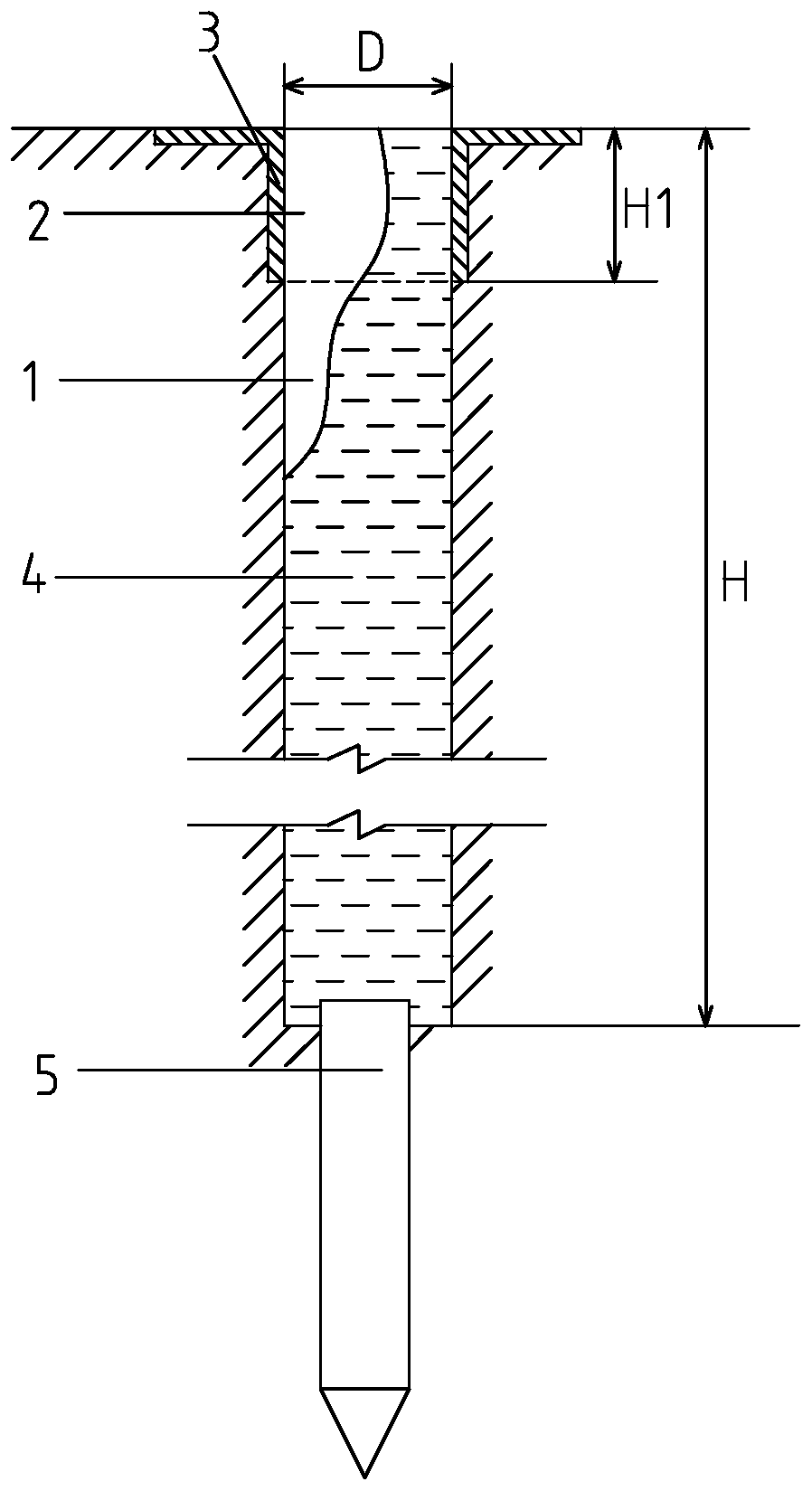
[0040] Such as figure 1 with figure 2 A kind of integral underground wall construction method shown, comprises the following steps: a, slotting, slotting on the ground by slotting machine, open the groove 1 that predetermined depth is H, width is D, in this embodiment by figure 1 Take the back-shaped groove shown in as an example, step a includes the following steps: a1, positioning and setting out: set the positioning point at the track of the groove to be opened on the ground, connect the positioning point with the positioning line to form the groove track, and Sprinkle gray lines along the positioning line to form a groove track; a2. Use a slotting machine to open a mud guide groove with a depth of H1 and a width of D along the groove track. The ratio of the depth H1 of the mud guide groove to the predetermined depth H is 0.07 -0.15; a3. Concr...


PUM


Abstract

The invention relates to the technical field of underground construction, and discloses an integral underground wall construction method. The integral underground wall construction method comprises the following steps that a, slotting is conducted; b, pulping is conducted; c, wall preparing and sinking are conducted, a plurality of cranes are arranged at the position, above a groove, of the ground, a supporting plate is arranged on the top of the groove and fixed to the lower end of a sling on each crane, a first wall is formed on the supporting plate through concrete pouring, after the firstwall is dismounted, the slings of all the cranes synchronously descend, and a second wall is formed on the top face of the first wall in a pouring manner; and after the second wall is dismounted, a third wall is arranged on the top face of the second wall in a pouring manner, in a similar way, the multiple walls are sequentially connected and gradually sunk into the groove till the total height ofthe walls reaches the preset height H. An underground wall manufactured through the construction method is high in quality and free of seepage, secondary construction is avoided, the construction cost is greatly reduced, and the construction period is effectively shortened.

Description

technical field [0001] The invention relates to the technical field of underground construction, in particular to an integral underground wall construction method. Background technique [0002] With the development of society, urban construction is changing with each passing day, and there are more and more underground projects, such as high-rise building basements, underground corridors, multi-storey underground garages, subway tunnels and other underground construction projects. These projects are all deep foundation construction. In order to ensure the safety of construction and the safety and stability of the surrounding environment, it is necessary to carry out foundation pit enclosure, and dig the foundation pit after the foundation pit enclosure. [0003] At present, the foundation pit enclosure usually adopts the scheme of pile row wall plus internal support or pile row wall plus external cable, but the pile row wall is a temporary support structure. After the constr...

Claims


Application Information

Patent Timeline
Patent Type & Authority Patents(China)
IPC IPC(8): E02D5/18
Inventor 章胜南吴朝峰孙正东
Owner 章胜南
Why Eureka
Try Eureka