
Self-reset buckling limitation support

A buckling restraint and self-resetting technology, applied to building components, earthquake resistance, etc., can solve problems such as poor restraint, limited deformation capacity of restrained supports, failure of failure, etc., to eliminate residual deformation, increase deformation range, and broaden the selection range Effect

Active Publication Date: 2015-07-01
SOUTHEAST UNIV
View PDF12 Cites 0 Cited by
  • Summary
  • Abstract
  • Description
  • Claims
  • Application Information

AI Technical Summary

Problems solved by technology

[0006] The technical problem to be solved by the present invention is to provide a self-resetting buckling-restrained support that doubles the ultimate deformation capacity of the self-resetting buckling-restrained support and precisely restrains the buckling of the energy-dissipating inner core plate to solve the problems of the above-mentioned existing technologies. The problem of limited deformation capacity of the reset buckling restrained brace and failure due to poor restraint of the energy-dissipating inner core plate, and at the same time broaden the selection range of self-resetting buckling restrained braces for reinforcements, and facilitate the mixed use of different reinforcements

Method used


Image

  • Self-reset buckling limitation support
  • Self-reset buckling limitation support
  • Self-reset buckling limitation support

Examples


Embodiment 1

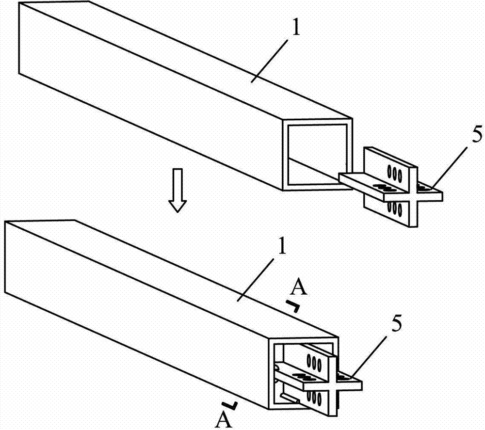
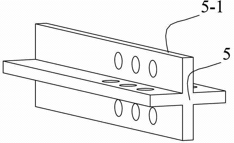
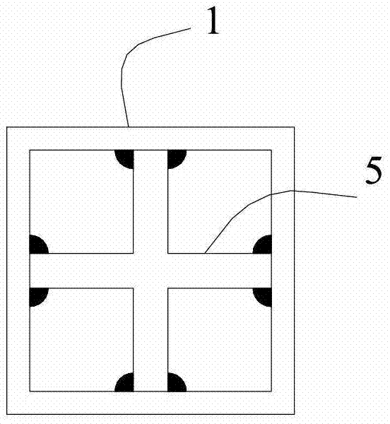
[0046] Embodiment one: if Figure 1~21 As shown, the self-resetting buckling restraint support of this embodiment consists of two energy-dissipating inner core plates 2, an inner restraint force transmission component 1, an intermediate restraint force transmission component 3, an outer force transmission component 4, an inner connector 5, and two outer connectors 6. The first set of ribs 7, the first set of end plates 8, the second set of ribs 9, and the second set of end plates 10, the energy-dissipating inner core plate 2 is connected by the inner core plate 2-1 and the end Composed of plates 2-2, one side of the end connecting plate 2-2 is welded to the surface of one end of the inner core plate 2-1 through a weld along the long side direction, and the internal constraint force transmission component 1 is located on two energy-dissipating inner core plates 2 On the inner side, the inner connecting piece 5 is welded to the inner side of one end of the inner constraint force...

Embodiment 2

[0048] Embodiment two: if Figure 19~21 As shown, each second group of end plates 10 and one first group of end plates 8 in this embodiment are in the same plane, and each second group of end plates 10 and each first group of end plates 8 in the same plane There is a gap of 1-2 mm on the outer edge of each of the first group of end plates 8 simultaneously contacting the inner constraint force transmission part 1 and the middle constraint force transmission part 3, and each second group of end plates 10 simultaneously contacting the middle constraint force transmission part 3 and external power transmission component 4. Other composition and connection methods are the same as those in Embodiment 1.

Embodiment 3

[0049] Embodiment three: as Figure 9 As shown, the shape of each filling plate 3-2 in this embodiment corresponds to the side shape of each energy-dissipating inner core plate 2, and each filling plate 3-2 is located between two channel-shaped steel plates 3-1 and two In the middle of each cover plate 3-3, every two filling plates 3-2 are located on the upper and lower surfaces of two channel steels 3-1, and the outside of every two filling plates 3-2 is a cover plate 3-3, the filling plate The gap between 3-2 and cover plate 3-3 and the energy-dissipating inner core plate 2 is about 1-2mm, and the in-plane and out-of-plane buckling of the energy-dissipating inner core plate 2 are restrained at the same time, and there is no need to set special restraining parts to restrain the energy-dissipating inner core Buckling of plate 2; the entire middle restraint force transmission part 3 has no contact with the inner restraint force transmission part 1, the energy-dissipating inner ...


PUM


Abstract

The invention discloses a self-reset buckling limitation support. The self-reset buckling limitation support comprises an energy-consuming inner core plate, a force transmission part, a rib material and an end plate, wherein the force transmission part comprises an inner limitation force transmission part, a middle limitation force transmission part and an outer force transmission part; one end of the energy-consuming inner core plate is fixed at the upper and lower side surfaces of the inner limitation force transmission part while the other end of the energy-consuming inner core plate is fixedly connected to the outer force transmission part; the middle limitation force transmission part is sleeved outside the inner limitation force transmission part and the energy-consuming inner core plate, and has a gap with the inner limitation force transmission part and the outer limitation force transmission part in the circumferential direction; the inner limitation force transmission part is internally provided with a first group of rib materials which is fixed through a first group of end plates; and a second group of rib materials which is fixed through a second group of end plates is arranged between the middle limitation force transmission part and the outer force transmission part. The self-reset buckling limitation support can increase the supported deformation capability to be a few times the ultimate elastic deformation range of the rib materials, and is satisfied with the need of the structural design more easily.

Description

technical field [0001] The invention belongs to the field of civil engineering and relates to a self-resetting buckling constrained support for reducing the impact of earthquake disasters on engineering structures. Background technique [0002] Buckling restrained bracing is a device that uses metal yielding to dissipate seismic energy. Due to its stable performance, convenient fabrication, and low cost, it has been widely studied and applied in recent years. However, since the buckling-constrained bracing utilizes the tensile and compressive yield of the core metal plate to dissipate the seismic energy, the bracing itself will produce cumulative plastic deformation, resulting in non-negligible residual deformation of the structure, which seriously affects the post-earthquake use and safety performance of the structure. Therefore, a self-resetting buckling-restrained brace that uses pre-tensioned tendons to provide self-resetting pressure for the buckling-restrained brace ha...

Claims


Application Information

Patent Timeline
Patent Type & Authority Patents(China)
IPC IPC(8): E04B1/98
Inventor 王春林曾鹏周臻吴京葛汉彬
Owner SOUTHEAST UNIV
Learn More