
Patient circuit integrity alarm using exhaled CO2

A technology of carbon dioxide and alarms, which is applied in alarms, respirators, medical devices, etc., and can solve problems such as difficulty in implementation, failure of alarm mechanisms, and occlusions

Active Publication Date: 2013-03-27
维亚埃尔医疗211公司
View PDF7 Cites 2 Cited by
  • Summary
  • Abstract
  • Description
  • Claims
  • Application Information

AI Technical Summary

Problems solved by technology

When the breathing tube is dislodged, for example by resting on the patient's face, it may remain occluded or partially occluded, causing the alarm mechanism to fail
Furthermore, these complex algorithms may be difficult to implement in a ventilator

Method used


Image

  • Patient circuit integrity alarm using exhaled CO2
  • Patient circuit integrity alarm using exhaled CO2
  • Patient circuit integrity alarm using exhaled CO2

Examples


Embodiment Construction

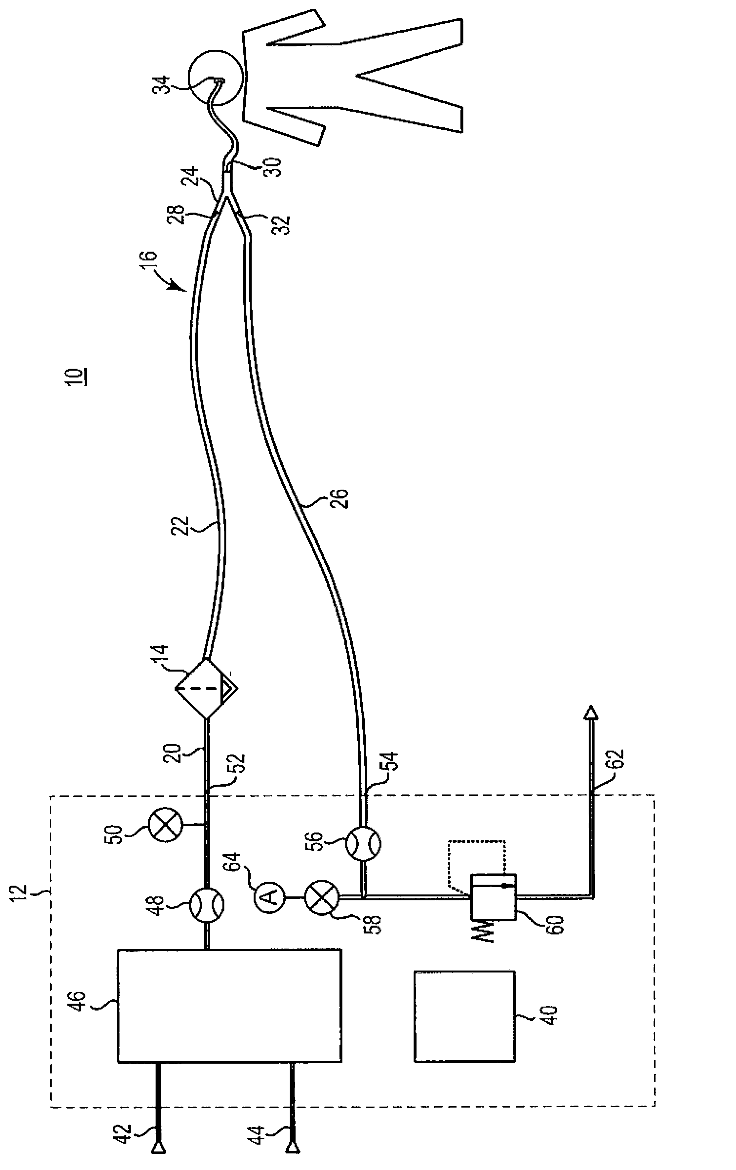
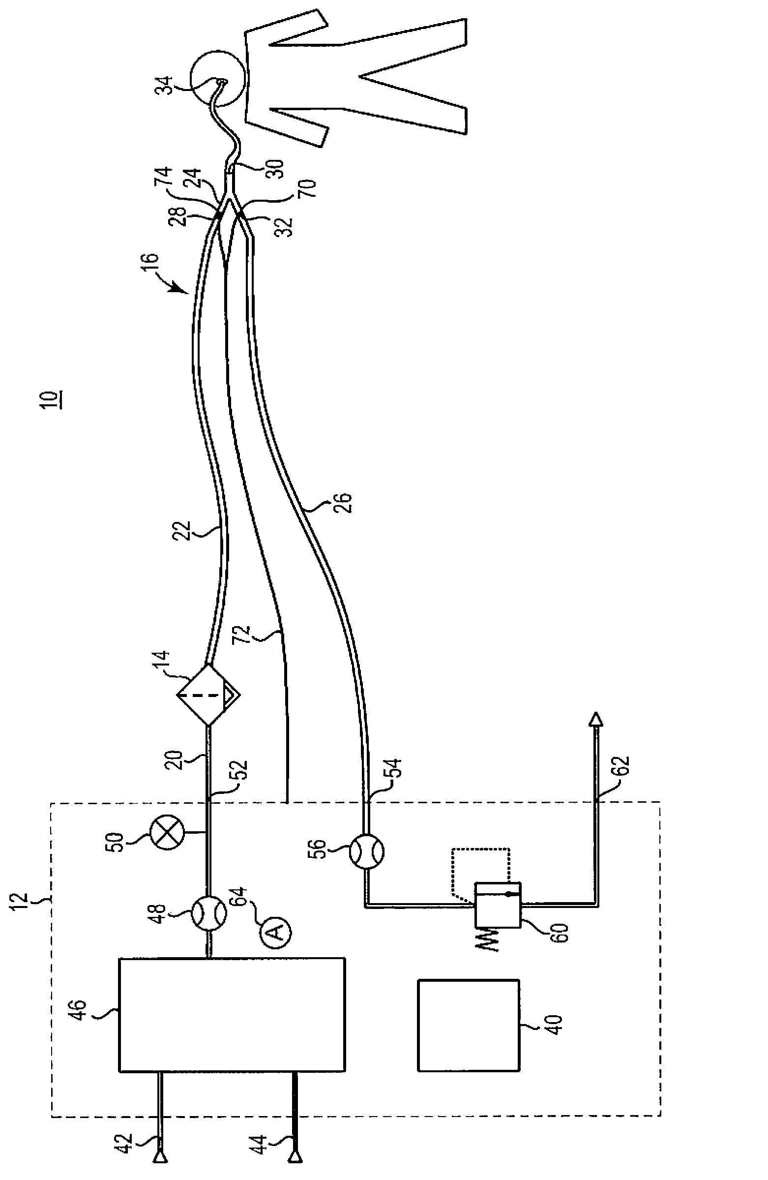
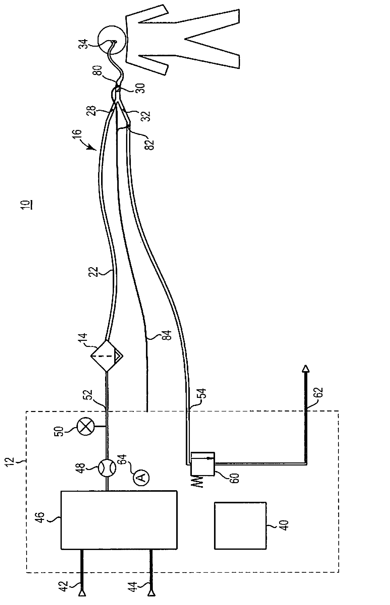
[0012] figure 1 is a schematic diagram of a respiratory therapy system 10 including a ventilator 12 , an optional humidifier 14 and a patient circuit 16 . It is worth noting that respiratory therapy system 10 is one embodiment of the inventive concepts presented herein. For example, other forms of respiratory therapy may be used with the concepts presented herein, such as CPAP (continuous positive airway pressure) systems or other systems that may add or delete one or more components of system 10 . In the illustrated embodiment, ventilator 12 supplies gas to humidifier 14 through initial conduit 20 . Humidifier 14 heats the water within the humidification chamber to form water vapor which is mixed with the gas provided by ventilator 12 and the mixed mixture is then output to patient circuit 16 . Patient circuit 16 includes an inspiratory conduit (or branch) 22 , a Y-connector 24 and an expiratory conduit (or branch) 26 . In some alternative embodiments, for example, in a CP...


PUM


Abstract

A carbon dioxide sensor for use in a respiratory therapy system. The carbon dioxide sensor determines whether a patient interface is fluidly coupled to a patient.

Description

Background technique [0001] Lung ventilators provide therapeutic gas (eg, oxygen) and pressure-volume support to the patient's lungs to facilitate gas exchange with the patient by supporting spontaneous breathing or providing mandatory breathing in the absence of spontaneous breathing. Gas is provided to the patient through an inspiratory tube, and the ventilator is fluidly coupled to the lungs through the use of a patient interface such as an endotracheal tube, nasal cannula, or mask. There is a risk that the fluid connection between the ventilator and the lungs may be lost, for example due to patient movement causing the patient interface to become detached. If the connection between the patient interface and the patient is severed, loss of breath could harm the patient. [0002] Current ventilators detect this lost breath by using complex algorithms based on measuring the pressure and flow of the breathing circuit. These algorithms can fail in cases of significant leakage...

Claims


Application Information

Patent Timeline
IPC IPC(8): A61M16/06A61M16/10A61M39/10G08B21/02
CPCA61M2205/18A61M16/0051A61M2016/209A61M2016/103A61M2016/0027A61M2016/0021A61M2016/0833A61M2016/0039A61M2016/0042A61M2016/0036A61M2230/432A61M16/06A61M16/12A61M2205/583A61M2205/13A61M16/16A61M16/0833A61M16/209A61M16/202A61M16/024
Inventor 保罗·大卫·狄克逊特里·李·布兰斯费尔德
Owner 维亚埃尔医疗211公司
Learn More