Secondary relief valve, hydraulic lowering system for cranes and crane

A secondary relief valve and relief valve technology, applied in the hydraulic field, can solve the problems of difficult control and different drop speeds, and achieve the effects of dynamic drop, improved drop speed, and good drop control performance.

Active Publication Date: 2013-04-03
SANY HEAVY IND CO LTD (CN)
View PDF6 Cites 9 Cited by
  • Summary
  • Abstract
  • Description
  • Claims
  • Application Information

AI Technical Summary

Problems solved by technology

The falling speed of this method is stable, but its falling speed is greatly affected by factors such as the hanging load, the extension angle of the boom, and the lubrication of the hinge point. The above-mentioned factors are different, and the falling speed will also be different, so it is not easy to control

Method used


Image

  • Secondary relief valve, hydraulic lowering system for cranes and crane
  • Secondary relief valve, hydraulic lowering system for cranes and crane
  • Secondary relief valve, hydraulic lowering system for cranes and crane

Examples


Embodiment Construction

[0020] It should be noted that, in the case of no conflict, the embodiments of the present invention and the features in the embodiments can be combined with each other. The present invention will be described in detail below with reference to the accompanying drawings and examples.

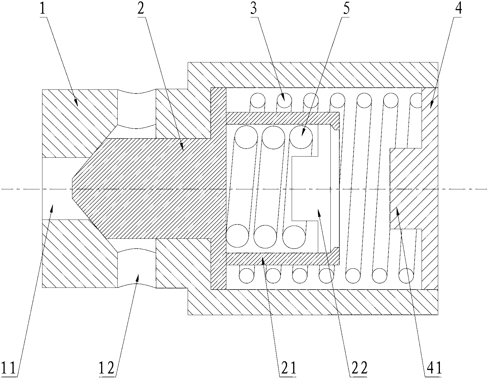
[0021] figure 1 and figure 2 That is, the relevant drawings of the embodiment of the secondary relief valve of the present invention, such as figure 1 As shown, the secondary relief valve includes a valve body 1, a valve core 2 and a pressure regulating device. The valve body 1 is provided with two oil outlets 12 and an oil inlet 11 coaxial with the valve core 2. The pressure regulating device includes a primary pressure regulating spring 3 coaxial with the spool 2, a secondary pressure regulating spring 5 and a pressure regulating plug 4. The diameter and length of the secondary pressure regulating spring 5 are smaller than the primary pressure regulating spring 3 , but its stiffness coeffic...


PUM


Abstract

The invention provides a secondary relief valve, a hydraulic lowering system for cranes and a crane. The secondary relief valve comprises a valve body, a spool and a pressure regulator, the pressure regulator comprises a first-stage pressure-regulating spring and a pressure-regulating plug which are coaxial with the spool, one end of the first-stage pressure-regulating spring abuts against the end of the spool, the other end of the first-stage pressure-regulating spring abuts against the pressure-regulating plug, the pressure regulator also comprises a second-stage pressure-regulating spring, the diameter and length of the second-stage pressure-regulating spring are less than the diameter and length of the first-stage pressure-regulating spring, and the stiffness coefficient of the second-stage pressure-regulating spring is greater than the stiffness coefficient of the first-stage pressure-regulating spring. The pressure-flow relation of the secondary relief valve has two states; when the secondary relief valve is applied on the hydraulic lowering system for cranes, the hydraulic lowering system for cranes has two lowering control modes, i.e. self-weight lowering and powered lowering; the self-weight lowering mode can be adopted for low-speed lowering in order to achieve good lowering control performance; if lowering needs to be accelerated, an accelerator can be stepped to increase flow, consequently, powered lowering is carried out, and the lowering speed is increased.

Description

technical field [0001] The invention relates to the field of hydraulic pressure, in particular to a secondary relief valve, a crane hydraulic system and a crane. Background technique [0002] There are two main types of existing crane hydraulic systems. One is the power drop system, that is, the rod cavity of the luffing cylinder enters the pressure oil, and the luffing cylinder is driven by hydraulic pressure to retract to realize the drop action. This method can control the falling speed, but because the volume of the rod cavity is small, and the flow of pressure oil connected is relatively large, so the fretting performance of this method is not good. jitter. The other is the self-weight drop system, and the rod chamber of the luffing cylinder is connected to the oil circuit, and the oil in the rodless chamber of the luffing cylinder returns to the oil under the self-weight of the boom and the load to realize the drop action. The falling speed of this method is stable,...

Claims


Application Information

Patent Timeline
Patent Type & Authority Applications(China)
IPC IPC(8): F15B13/02F15B11/02B66C13/20
Inventor 刘高丁锋李小飞
Owner SANY HEAVY IND CO LTD (CN)
Why Eureka
Try Eureka