Drive motor current signal acquisition device for transformer voltage regulating switch tap

A current signal acquisition and motor driving technology, applied in the direction of measuring devices, measuring current/voltage, instruments, etc., can solve the problems of dismantling, complicated wiring, long test time, and unfavorable on-site use, etc., to achieve simple and convenient on-site operation, Avoid safety hazards and facilitate connection

Active Publication Date: 2015-12-09
SHANGHAI MUNICIPAL ELECTRIC POWER CO +2
View PDF6 Cites 0 Cited by
  • Summary
  • Abstract
  • Description
  • Claims
  • Application Information

AI Technical Summary

Problems solved by technology

This method is unfavorable for on-site use due to complicated wiring and complicated wiring, and long test time.

Method used


Image

  • Drive motor current signal acquisition device for transformer voltage regulating switch tap
  • Drive motor current signal acquisition device for transformer voltage regulating switch tap
  • Drive motor current signal acquisition device for transformer voltage regulating switch tap

Examples


Embodiment

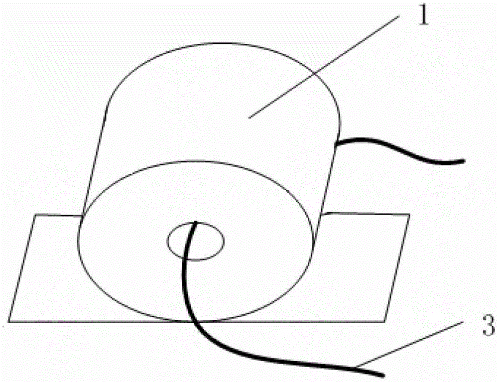
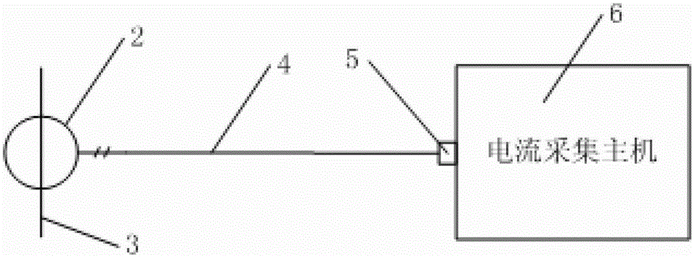
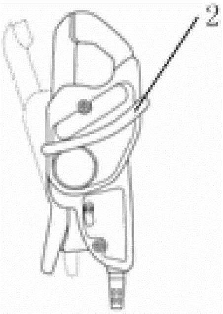
[0019] Such as figure 2 As shown, a current signal acquisition device for a drive motor of a tap of a voltage regulating switch of a transformer includes a clamp current sensor 2 , a coaxial cable 4 , a BNC connector 5 and a current acquisition host 6 . The specific structure of clamp current sensor 2 is as follows image 3 As shown, it is clamped on the power line 3 of the driving motor. If the driving motor is a single-phase motor, the clamp-on current sensor is clamped on the single-phase power line. If the driving motor is a three-phase motor, the clamp-on current sensor is clamped on any phase power line. In this way, the problem of needing to disconnect and connect the power cord on site is well solved.

[0020] The signal output end of the clamp current sensor 2 is connected to the current acquisition host 6 through the coaxial cable 4 and the BNC connector 5, and the collected current signal is transmitted to the current acquisition host. After the current acquisit...


PUM


Abstract

The invention relates to a driving motor current signal collection device of a transformer voltage regulating switch tap. The signal collection device comprises a current sensor and a current collection main machine. The current sensor is connected with a driving motor, the current collection main machine is connected with the current sensor, and the current sensor is a pincerlike current sensor and is clamped on a power wire of the driving motor. Compared with the prior art, the driving motor current signal collection device has the advantages of being simple in wire connection, convenient to use, high in accuracy and the like.

Description

technical field [0001] The invention relates to a signal acquisition device, in particular to a drive motor current signal acquisition device used for a tap of a voltage regulating switch of a transformer. Background technique [0002] By analyzing the current signal of the driving motor generated during the operation of the transformer on-load tap changer, some potential safety hazards of the on-load tap changer can be judged. The current acquisition method of the drive motor is to use a through-hole current sensor for measurement. The power line of the drive motor must be removed, and the power line must be passed through the measurement hole in the middle of the sensor. figure 1 shown. This method is unfavorable for on-site use due to its complicated wiring and complicated wiring and long test time. Therefore, it is necessary to invent a novel way of collecting the current signal of the drive motor. Contents of the invention [0003] The object of the present inventi...

Claims


Application Information

Patent Timeline
Patent Type & Authority Patents(China)
IPC IPC(8): G01R19/00
Inventor 廖天明高凯郭森蔡怡然邓敏倪浩陈璐
Owner SHANGHAI MUNICIPAL ELECTRIC POWER CO
Why Eureka
Try Eureka