
An anti-loosening plug and an electrical connector assembly using the same

A plug and anti-loosening technology, which is applied to the parts, connections, electrical components, etc. of the connection device, and can solve the problems such as the easy failure of the claw locking mechanism

Active Publication Date: 2015-09-23
CHINA AVIATION OPTICAL-ELECTRICAL TECH CO LTD
View PDF4 Cites 0 Cited by
  • Summary
  • Abstract
  • Description
  • Claims
  • Application Information

AI Technical Summary

Problems solved by technology

[0004] The purpose of the present invention is to provide an anti-loosening plug to solve the problem that the claw locking mechanism of the existing electrical connector is prone to failure

Method used


Image

  • An anti-loosening plug and an electrical connector assembly using the same
  • An anti-loosening plug and an electrical connector assembly using the same
  • An anti-loosening plug and an electrical connector assembly using the same

Examples


Embodiment Construction

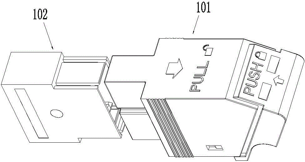
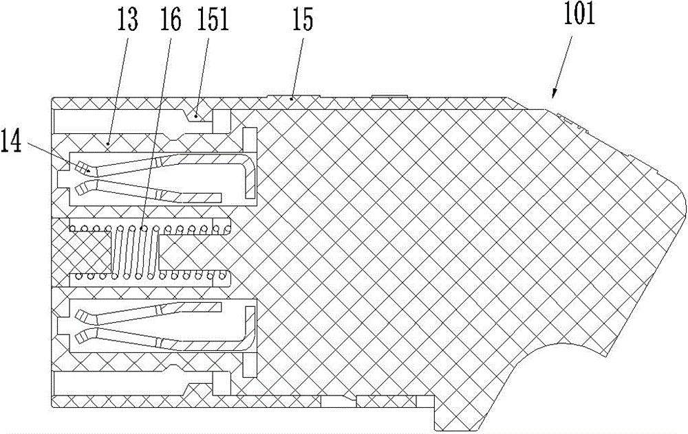
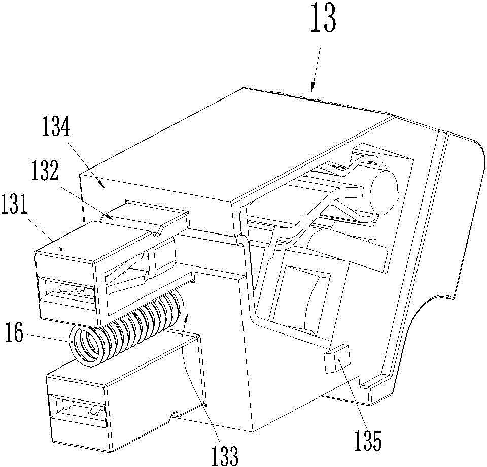
[0026] Embodiment 1 of the electrical connector assembly of the present invention, such as Figure 1-8As shown, it includes a plug 101 and a socket 102. The plug 101 and the socket 102 respectively use their respective front ends as plug-in ends, wherein the socket 102 includes a socket housing 11, and the front end (plug-in end) of the socket housing 11 has a plug-in channel. 111, wherein the socket contacts 12 are fixedly installed. In this embodiment, there are two socket contacts 12. In addition, the front end of the socket housing 11, that is, the periphery of its insertion channel, is provided with a claw 112, and the claw 112 The front end of the socket has a claw protruding inward, and an anti-misplug key 113 is also provided on the outer wall surface at the front end of the socket housing 11; the plug 101 includes a plug housing 13, and the front end (plug end) of the plug housing 13 has The plug-in section is used to be inserted into the plug-in channel of the socket...


PUM


Abstract

The invention relates to the field of electric connectors, and in particular relates to a locking plug and an electric connector assembly using the same. The front end of the locking plug is used as an insertion end. The locking plug comprises a plug shell, and a lock sleeve movably sleeved on the plug shell in a front-back locking manner, the front end of the plug shell is provided with an insertion section used for being inserted into an adaptive socket, at least one lock groove for pivoting elastic jaws adapted on the socket is arranged in the outer wall surface of the insertion section, a gap in which the plug shell can enter is arranged between the outer wall surface of the insertion section and the inner wall surface of the lock sleeve, a push spring is supported and arranged between the lock sleeve and the plug shell, the push spring forwards pushes the lock sleeve, an inwards convex locking platform is arranged on the inner wall surface of the lock sleeve, and when the plug is inserted with the adaptive socket and the elastic jaws on the adaptive socket are pivoted in the corresponding lock grooves, the locking platform is positioned at the periphery corresponding to the elastic jaws and is used for limiting the deformation of the elastic jaws to the circumferential periphery of the plug. The locking plug solves the problem that an elastic jaw locking mechanism of the existing electric connector is easy to fail.

Description

technical field [0001] The invention relates to the field of electrical connectors, in particular to an anti-loosening plug and an electrical connector assembly using the plug. Background technique [0002] In some occasions where vibration or dragging is required, it is necessary to have a certain locking mechanism between the plug and the socket of the electrical connector assembly, and the claw locking mechanism is the more common one of the above-mentioned locking mechanisms. The mechanism refers to the insertion part used to be inserted into the insertion channel of the socket at the front end of the plug housing, and the locking claw is set on the insertion part. The fingertip of the locking claw extends forward, and the back of the fingertip There is a wedge, the front side of the wedge is a slope that gradually climbs from the front to the rear to the back of the locking claw where it is located, and the outer part of the socket is equipped with an unlocking piece th...

Claims


Application Information

Patent Timeline
Patent Type & Authority Patents(China)
IPC IPC(8): H01R13/639H01R13/633H01R24/00
Inventor 吴泽华张春建
Owner CHINA AVIATION OPTICAL-ELECTRICAL TECH CO LTD
Learn More