Support assembly for dismantling of support beams in foundation pits

A technology for supporting components and supporting beams, applied in infrastructure engineering, construction, excavation, etc., can solve problems such as uncontrollable safety and reliability at the cutting site, unbalanced force on the main body of the inner supporting beam, and increasing the probability of safety accidents. , to achieve the effect of convenient hoisting and transportation, ensuring stability and reducing the probability of occurrence

Active Publication Date: 2019-08-30
CHINA MCC5 GROUP CORP
View PDF7 Cites 0 Cited by
  • Summary
  • Abstract
  • Description
  • Claims
  • Application Information

AI Technical Summary

Problems solved by technology

In view of the prior art, when the segmental demolition process is started along the cutting seam of the inner support beam, the stress generated by the interaction between the inner support beam and the sawing equipment will easily lead to the deviation of the uncut part of the inner support beam, and in severe cases, it will lead to The support beam is detached from the support plane, which increases the probability of safety accidents; moreover, the traditional support platform adopts the horse stool cap welded by channel steel. Square wooden plugs are used on the upper surface of the platform, but the square wooden plugs are easily affected by the vibration generated during cutting. After the offset occurs, there will be a gap between the horse stool cap and the inner support beam, causing the main part of the inner support beam to be stressed Unbalanced, and the fracture point of the inner support beam cannot be predicted, making the safety and reliability of the cutting site uncontrollable; in this regard, the applicant designed a support assembly specially used for cutting the inner support beam based on the above-mentioned defects in the prior art , that is, it includes a support platform and feet made of steel, and there are multiple grooves on the support plane on the support platform. The lower end of the screw is connected to the output end of the motor, and the upper end of the screw is connected to a fixed top plate. The screw part in the groove is provided with a lifting top plate that fits with the screw thread, and the upper end of the spring that is always in a compressed state is in contact with the bottom of the lifting top plate, that is, when the height of the support platform or the height of the fixed top plate is at the same position as the bottom surface of the inner support beam. When the horizontal height is the same, the upper surface of the support platform and the fixed top plate provide support for the inner support beam. When a certain stress is generated during cutting, the compressed spring will provide an elastic force opposite to the stress on the lifting top plate and the screw, that is, it can Eliminate the acting stress on the fixed top plate and the support plane to ensure the stability of the inner support beam during the cutting process; when the height of the support platform or the height of the fixed top plate is less than the level of the bottom surface of the inner support beam, start the motor, The screw starts to rotate, and the lifting top plate cooperates with the screw rod, and starts to rise under the guidance and restriction of the guide rail, while the lifting top plate rises, the fixed top plate remains motionless, and the circular groove moves up to completely wrap the fixed top plate , according to the height difference value between the fixed roof and the bottom of the inner support beam, the upward movement of the lifting roof is determined. The support of the support beam, and during the cutting process, the lifting top plate and the support platform form a whole, which are respectively restricted by the groove and the screw. Compared with the traditional square wooden plug, the lifting top plate will not have any deviation, and when cutting When a certain acting stress is generated, the springs that are always in a compressed state can also provide stress buffering for the lifting top plate, thereby ensuring the stability of the lifting top plate in the vertical direction, so that the inner support beam is cut along the cutting seam to form multiple sections of the same size. Small sections to facilitate later hoisting and transshipment, while ensuring the safety of construction personnel during the cutting process and reducing the probability of safety accidents

Method used


Image

  • Support assembly for dismantling of support beams in foundation pits
  • Support assembly for dismantling of support beams in foundation pits
  • Support assembly for dismantling of support beams in foundation pits

Examples


Embodiment 1

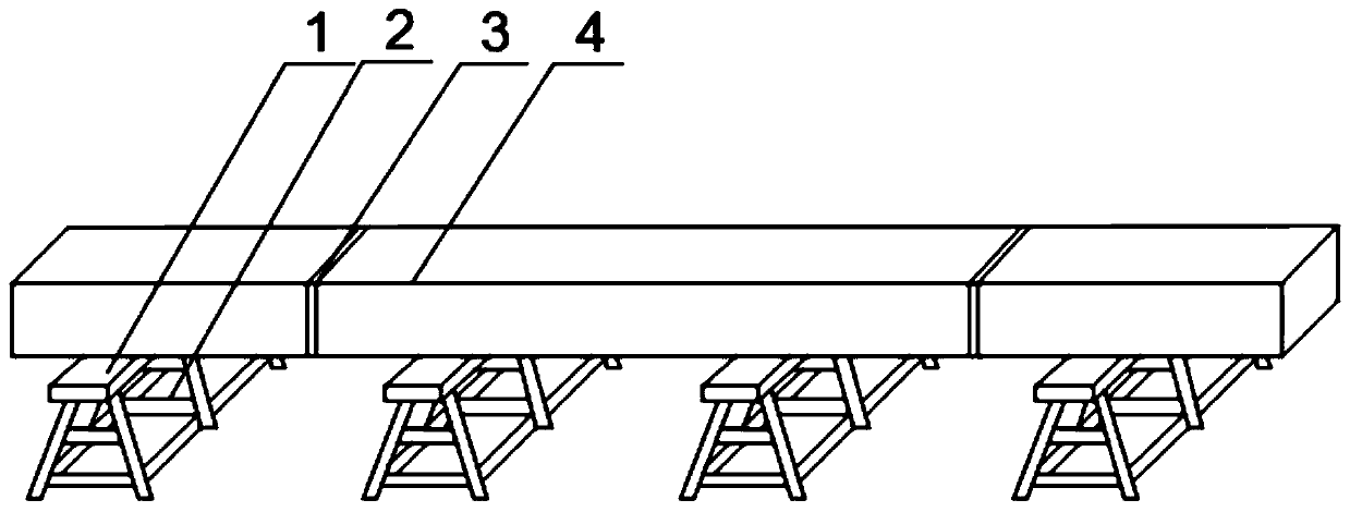
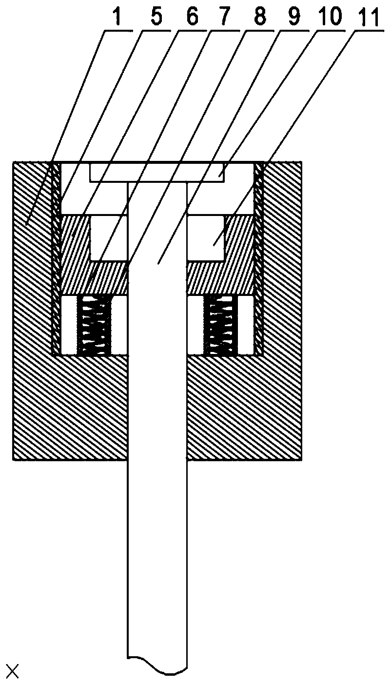
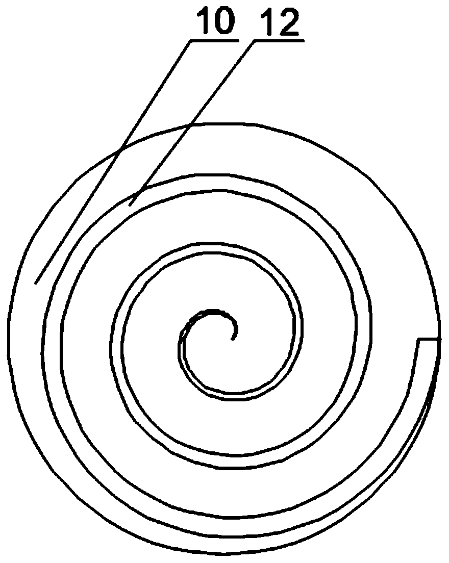
[0024] like Figure 1~4As shown, this embodiment includes a support platform 1 and a plurality of feet 2 arranged at the bottom of the support platform 1, a plurality of grooves are opened on the upper surface of the support platform 1, and a screw 9 moves through the lower surface of the support platform 1 After entering the groove, a circular fixed top plate 10 is installed on the upper end of the screw rod 9, and the outer peripheral wall of the screw rod 9 is provided with a lifting top plate 6 that cooperates with it, and the lifting top plate 6 is placed in the groove. 6 The upper surface is provided with a circular groove 11 coaxial with the screw rod 9, the outer diameter of the fixed top plate 10 is smaller than the inner diameter of the circular groove 11, and the axial depth of the circular groove 11 is greater than the axial depth of the fixed top plate 10 The length also includes a plurality of sleeves 7 arranged at the bottom of the groove, one end of the spring ...

Embodiment 2

[0027] like Figure 1~4 As shown, the upper surface of the fixed top plate 10 in this embodiment is equal to the upper surface of the supporting platform 1 . Further, the upper surface of the fixed top plate 10 is at the same level as the upper surface of the support platform 1, so that when the height of the upper surface of the support platform 1 is exactly the same as the height of the bottom of the inner support beam 4, the height of the inner support beam 4 Two different support surfaces are formed under the bottom, and the interaction between the fixed top plate 10 and the spring 8 can offset the stress generated during cutting to a certain extent, thereby increasing the support stability of the inner support beam 4 .

[0028] Further, the relationship between the axial length of the fixed top plate 10 and the axial depth of the circular groove 11 directly affects the height variation range of the support surface formed by the lifting top plate 6, and the axial length of...


PUM


Abstract

The invention discloses a supporting assembly for removing a supporting beam in a foundation pit. The supporting assembly comprises bearing tables and a plurality of supporting legs. A plurality of grooves are formed in the upper surfaces of the bearing tables. Screw rods movably penetrate through the lower surfaces of the bearing tables and then enter the corresponding grooves. Round fixing top plates are installed at the upper ends of the screw rods. Lifting top plates are arranged on the peripheral walls of the screw rods and are arranged in the corresponding grooves. Round grooves are formed in the upper surfaces of the lifting top plates. The axial depth of the round grooves is larger than the axial length of the fixing top plates. Guide rails are arranged on the inner walls of the grooves in the axial directions of the screw rods. The outer walls of the lifting top plates are provided with openings. In the cutting process, the lifting top plates and the bearing tables form a whole and are limited by the grooves and the screw rods. Compared with a traditional square wooden plug, the lifting top plates cannot offset; and moreover, when a certain action stress is generated in the cutting process, springs which are in a compressed state all the time can still provide stress buffer for the lifting top plates, and therefore the stability of the lifting top plates in the vertical direction is guaranteed.

Description

technical field [0001] The invention relates to the field of building construction, in particular to a support assembly used for removing support beams in foundation pits. Background technique [0002] The foundation pit support is to ensure the safety of the underground structure construction and the surrounding environment of the foundation pit, and the support, reinforcement and protection measures adopted for the side wall of the foundation pit and the surrounding environment. The support in the foundation pit is a kind of foundation pit support. After the construction of the underground structure in the foundation pit is completed, and the gap between the foundation pit and the outer wall of the underground structure is backfilled, the internal support needs to be removed. The internal support beam is one of the main components of the internal support structure. When removing the internal support beam, it is necessary to remove the small beam first, then the main beam;...

Claims


Application Information

Patent Timeline
Patent Type & Authority Patents(China)
IPC IPC(8): E02D17/04
Inventor 杨忠富张建江林文祥白松高长玲
Owner CHINA MCC5 GROUP CORP
Why Eureka
Try Eureka