

Transfer device and assembly device
A conveying device and conveying mechanism technology, applied in the field of assembling devices, can solve the problems of quality stability, increase the possibility of operator error, etc., and achieve the effect of improving productivity
- Summary
- Abstract
- Description
- Claims
- Application Information
AI Technical Summary
Problems solved by technology
Method used
Image

Examples
Embodiment approach 1
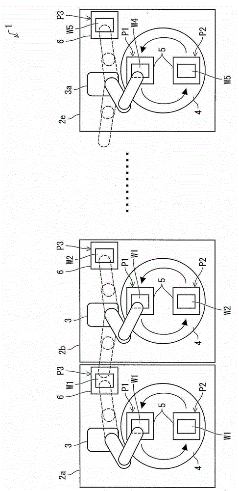
[0138] figure 1 It is a schematic block diagram of the conveyance apparatus 1 which connected five conveyance units.
[0139] As shown in the figure, five conveyance units 2a, 2b, . . . , 2e are connected and used. Each of these conveyance units is responsible for various assembling processes in the assembling process of the liquid crystal display device.
[0140] In this embodiment, five conveyance units 2a, 2b, . Figure 20 (e), (f), (g), (h) and (i) correspond to five kinds of assembling processing (processing) in the liquid crystal display device assembling process shown in (e), (f), (g), (h) and (i). The number of connected conveyance units is not particularly limited, and may be appropriately determined as needed.
[0141] Each of the transfer units 2a, 2b, . The workpiece table 6 is used to temporarily place the workpieces W1 , W2 , . . . , W5 to be processed in the assembly process. The calibration robot is used to transfer the workpieces W1, W2, . It is transfer...
Embodiment approach 2
[0223] Below, according to Figure 14 and Figure 15 A second embodiment of the present invention will be described. The conveying apparatus 1e of this embodiment differs from Embodiment 1 in that it is provided with a conveying unit 2f capable of performing an assembling operation. The conveying unit 2f includes a calibration robot 3 and two rotary indexing discs 4 and 4a (second conveying mechanism). and the 3rd transfer mechanism). The other structures are the same as those described in Embodiment 1. FIG. For convenience of description, components having the same functions as those shown in Embodiment 1 above are given the same reference numerals, and their descriptions are omitted.
[0224] Figure 14 It is a schematic block diagram of the conveyance apparatus 1e provided with the conveyance unit 2f which has the calibration robot 3 and the two rotary indexing discs 4 and 4a. like Figure 14 As shown, in the conveyance unit 2f, the assembly processing position P6 is ...
Deformed example 2-1
[0239] The following description Figure 14 Another modification of the conveying device 1e shown. Figure 16 (a) is the conveyance unit 2f with which the conveyance apparatus of this modification 2-1 is equipped 1 top view of the structure. In addition, regarding the bonding process between the liquid crystal display panel and the backlight unit (using the conveyance unit 2f 1 The steps after the processing to be performed) have been described above, so the description is omitted here.
[0240] like Figure 16 As shown in (a) of , in the conveying apparatus of Modification 2-1, the conveying unit 2f 1 Instead of the rotary index plate 4a, an inversion index plate 4b having an inversion mechanism is provided as a third conveyance mechanism. The reversing index plate 4b includes a reversing mechanism 23 . The inversion mechanism 23 inverts the top and bottom surfaces of the liquid crystal display panel 100 while moving the liquid crystal display panel 100 (workpiece) from...
PUM
 Abstract
Description
Claims
Application Information