
Method of controlling vehicle wheel axle torque and control system for same

A shaft torque, torque limiting technology, applied in the field of direction propulsion

Active Publication Date: 2013-04-17
GM GLOBAL TECH OPERATIONS LLC
View PDF3 Cites 8 Cited by
  • Summary
  • Abstract
  • Description
  • Claims
  • Application Information

AI Technical Summary

Problems solved by technology

Therefore, the possibility exists to propel the vehicle in the opposite direction to the intended motion

Method used


Image

  • Method of controlling vehicle wheel axle torque and control system for same
  • Method of controlling vehicle wheel axle torque and control system for same
  • Method of controlling vehicle wheel axle torque and control system for same

Examples


Embodiment Construction

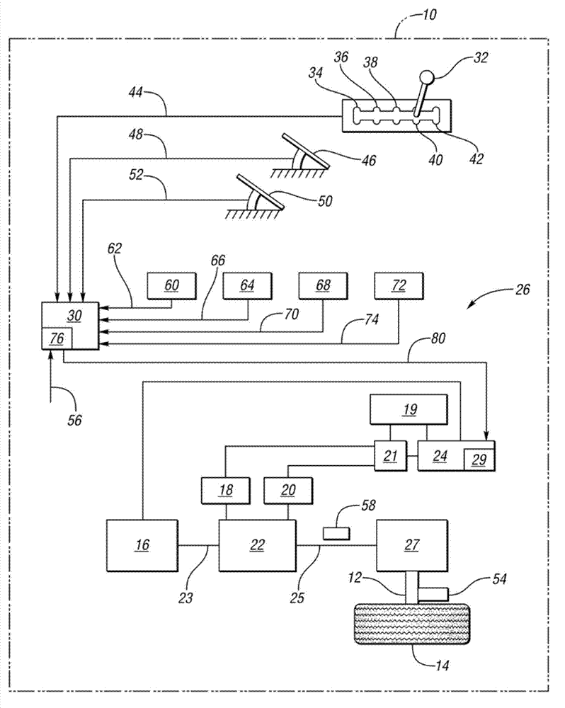
[0016] Referring to the drawings, wherein like reference numerals denote like parts throughout the several views, figure 1 A vehicle 10 is shown being propelled when axle torque is provided to axles 12 of wheels 14 . Only one axle 12 is shown. Vehicle 10 may be a front-wheel drive, rear-wheel drive, or all-wheel drive vehicle within the scope of the claimed invention. As shown, the vehicle 10 is a hybrid vehicle having an engine 16 and two motor / generators 18 , 20 . However, vehicle 10 may alternatively be an electric vehicle, having a motor / generator but no engine, or may be a fuel cell vehicle, having only a fuel cell powering one or more electric motor / generators. The vehicle 10 can have multiple modes of operation, depending on the engagement of clutches or brakes in the transmission 22, and depending on whether the engine 16 is running and whether the motor / generators 18, 20 are each separately controlled to operate as a motor or Runs as a generator.

[0017] The engi...


PUM


Abstract

A method of controlling torque on a vehicle wheel axle includes comparing a torque intervention request to a predetermined minimum axle torque for a current vehicle speed and a current direction of motion of the vehicle. The predetermined minimum axle torque decreases as vehicle speed in an operator-selected direction of motion increases. An arbitrated axle torque is calculated based on an operator-requested torque, the current vehicle speed, the current direction of motion, and the greater of the torque intervention request and the predetermined minimum torque. Axle torque is applied to the vehicle's wheel axle based at least partially on the arbitrated axle torque.

Description

technical field [0001] The present invention relates to a method of controlling wheel axle torque and a control system therefor, in particular for preventing propulsion in a direction opposite to the intended direction of motion. Background technique [0002] The intended direction of motion of the vehicle is determined by the driver of the vehicle, usually by the position of the driver's gear lever position. No forward or reverse motion is intended by the driver when the shift lever is in the park or neutral position. When the driver has the shift lever position in the drive position (low range or manual), the intended direction of motion is the forward direction. When the driver has the shift lever position in the reverse position, the intended direction of motion is the reverse direction. [0003] Conventional powertrains are generally protected against movement in the opposite direction of intended movement because the engine cannot produce torque by itself rotating in...

Claims


Application Information

Patent Timeline
IPC IPC(8): B60W30/18
CPCB60K6/445B60W10/105B60W30/18036B60W2520/06B60W2520/10B60W2540/16B60W2710/105B60W20/30Y02T10/62
Inventor C.E.惠特尼R.B.杰斯D.阿布多T.R.德金
Owner GM GLOBAL TECH OPERATIONS LLC
Learn More