Exhaust gas recirculation apparatus for an engine
A technology of exhaust recirculation and exhaust recirculation valve, which is applied in the direction of engine components, engine control, combustion engine, etc., and can solve problems such as proper control of EGR valve
- Summary
- Abstract
- Description
- Claims
- Application Information
AI Technical Summary
Problems solved by technology
Method used
Image
Examples
no. 1 Embodiment approach
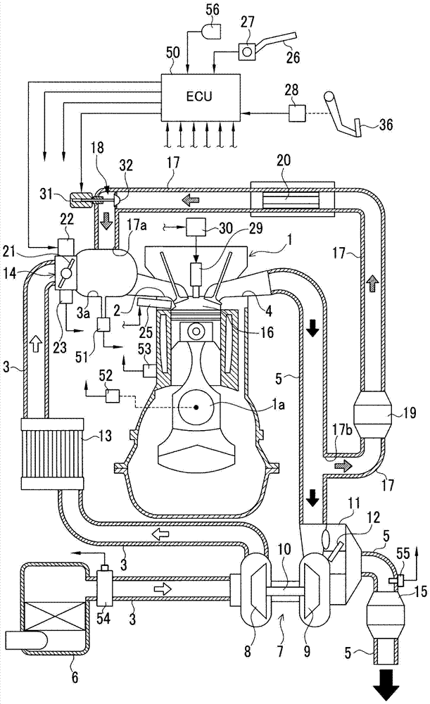
[0098] Hereinafter, a first embodiment in which the engine exhaust gas recirculation device of the present invention is embodied in a supercharger-equipped engine will be described in detail with reference to the accompanying drawings.
[0099] figure 1 An engine system including an exhaust gas recirculation device (EGR device) of the engine of this embodiment is shown in a schematic configuration diagram. The engine system includes a reciprocating engine 1 . An intake passage 3 is connected to the intake port 2 of the engine 1 , and an exhaust passage 5 is connected to the exhaust port 4 . An air cleaner 6 is provided at the inlet of the intake passage 3 . A supercharger 7 for boosting intake air in the intake passage 3 is provided between the intake passage 3 and the exhaust passage 5 at a portion downstream of the air cleaner 6 of the intake passage 3 .
[0100] The supercharger 7 includes a compressor 8 arranged in the intake passage 3 , a turbine 9 arranged in the exha...
no. 2 Embodiment approach
[0144] Next, a second embodiment in which the engine exhaust gas recirculation device of the present invention is embodied in a supercharger-equipped engine will be described in detail with reference to the accompanying drawings.
[0145] In addition, in each of the following embodiments, the same reference numerals are assigned to the same components as those of the above-described first embodiment, and the description thereof will be omitted, and the description will be focused on the differences.
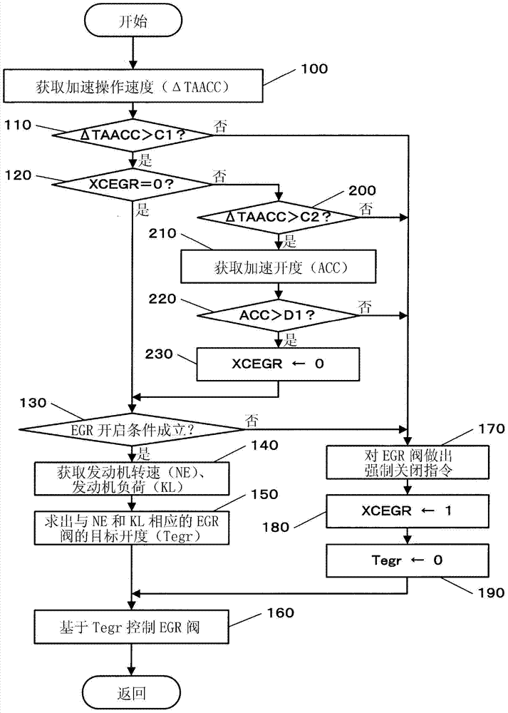
[0146] The present embodiment differs from the configuration of the first embodiment in the processing content of the EGR control. Image 6 An example of the processing contents of the EGR control of the present embodiment is shown by a flowchart. exist Image 6 The flow chart of the following aspects is related to image 3 The flow chart is different: Substitution image 3 The processing of step 110, step 200 and step 220 in the flow chart of the above, and the processing of ...
no. 3 Embodiment approach
[0163] Next, a third embodiment in which the engine exhaust gas recirculation device of the present invention is embodied in a supercharger-equipped engine will be described in detail with reference to the accompanying drawings.
[0164] The present embodiment differs from the configurations of the first embodiment and the second embodiment in the processing content of the EGR control. Figure 9 An example of the processing contents of the EGR control of the present embodiment is shown by a flowchart. exist Figure 9 The flow chart of the following aspects is related to Image 6 The flow chart is different: Substitution Image 6 The processing of step 111, step 170 and step 201 in the flowchart of the The processing of step 420 is added between 410 and step 171 , and the processing of step 430 is added between step 112 and step 171 .
[0165] That is, after obtaining the second deceleration determination value C2 based on the opening ratio Regr / TA in step 320 , the ECU 50 ...
PUM
 Abstract
Description
Claims
Application Information
 - R&D
- Intellectual Property
- Life Sciences
- Materials
- Tech Scout
- Unparalleled Data Quality
- Higher Quality Content
- 60% Fewer Hallucinations
Browse by: Latest US Patents, China's latest patents, Technical Efficacy Thesaurus, Application Domain, Technology Topic, Popular Technical Reports.
© 2025 PatSnap. All rights reserved.Legal|Privacy policy|Modern Slavery Act Transparency Statement|Sitemap|About US| Contact US: help@patsnap.com


