Locking and unlocking mechanism of power-driven sliding plug door

An electric plug door and unlocking mechanism technology, applied in the field of rail vehicles, can solve the problems of complex structure, poor reliability and safety, inconvenient installation and adjustment, etc., and achieve the effect of high safety, convenient installation and adjustment, and low cost

Active Publication Date: 2013-04-17
河北博得交通设备有限公司
View PDF5 Cites 23 Cited by
  • Summary
  • Abstract
  • Description
  • Claims
  • Application Information

AI Technical Summary

Problems solved by technology

The existing sliding door locking and unlocking mechanism has complex structure, inconvenient installation and adjustment, and poor reliability and safety

Method used


Image

  • Locking and unlocking mechanism of power-driven sliding plug door
  • Locking and unlocking mechanism of power-driven sliding plug door
  • Locking and unlocking mechanism of power-driven sliding plug door

Examples


Embodiment Construction

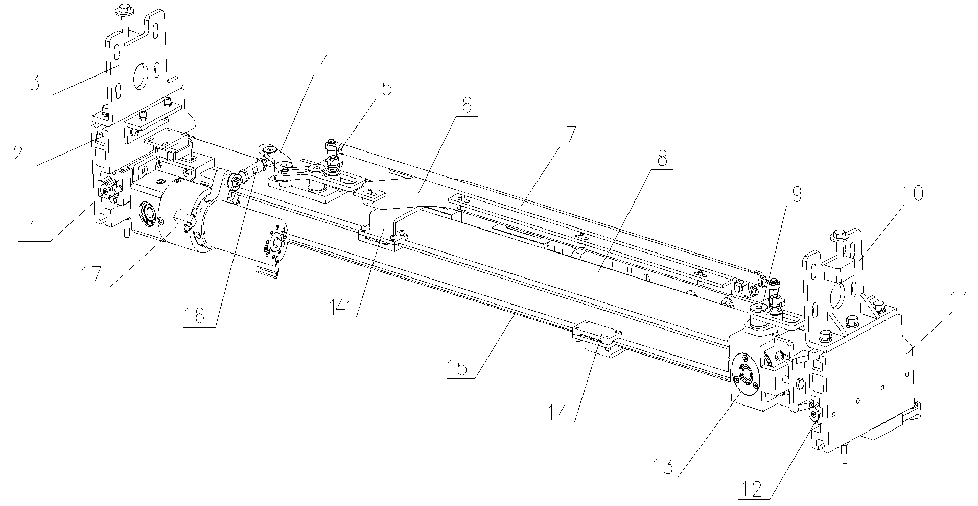
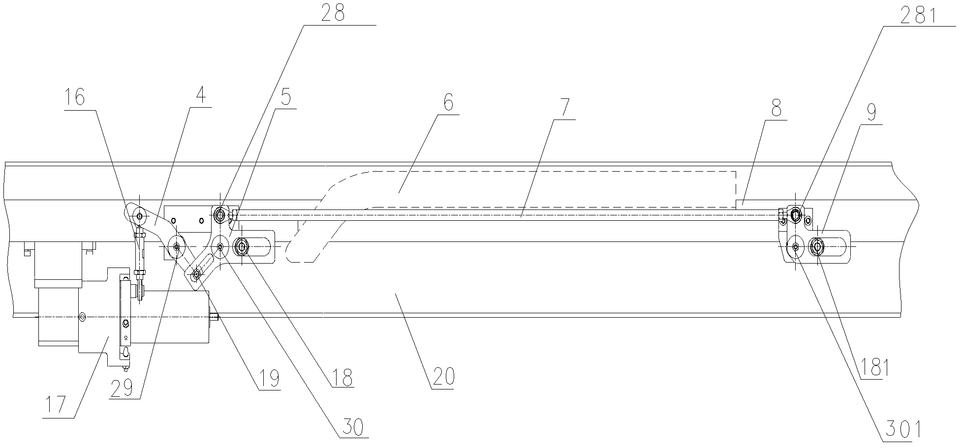
[0026] Such as figure 1 As shown, the drive control mechanism of the rail vehicle electric sliding door involved in the present invention includes a load beam 8, left and right support devices 2 and 11, left and right longitudinal guide rails 1 and 12, transverse guide rails, guide rails 6, motor swing rods Drive assembly 17, toothed belt 15, toothed belt connectors 14 and 141, driven end pulley part 13, upper support base plate 20 (see figure 2 ). in,

[0027] The inner sidewalls of the left and right supporting devices 2 and 11 are respectively provided with longitudinal guide rails 1 and 12 in the direction of plugging. The load-bearing beam 8 is a supporting profile, and its two ends are slidably connected to the left and right longitudinal guide rails 1 and 12 through sliders, and can slide along the left and right longitudinal guide rails 1 and 12, so that the overall mechanism Perform movement in the direction of Sierra. Left and right supporting devices 2 and 11 a...


PUM


Abstract

A locking and unlocking mechanism of a power-driven sliding plug door comprises a locking and unlocking assembly and a motor rocker driving assembly. The locking and unlocking assembly comprises an unlocking rocker, a left rocker, a right rocker, a draw bar and a knuckle bearing connection rod, wherein the locking and unlocking assembly is connected with the motor rocker driving assembly through the knuckle bearing connection rod; and the motor rocker driving assembly drives the locking and unlocking assembly to actuate through the knuckle bearing connection rod. When a door sash is opened, a motor rotates, and a casing of the motor rotates reversely due to overlarge resistance to drive the driving rocker and the unlocking rocker to swing, so that the unlocking rocker passes through a locking dead point in swinging mode to achieve unlocking; and when the door sash is closed, the unlocking motor rotates reversely, when the unlocking motor reaches the position the door sash needs to be closed, the casing of the motor rotates reversely due to increased door closing resistance to drive the driving rocker and the unlocking rocker to swing reversely, and when the unlocking rocker passes through the locking dead point, locking can be achieved. The locking and unlocking mechanism is simple in structure, low in cost, convenient to install and adjust, high in reliability and good in safety.

Description

technical field [0001] The invention belongs to the technical field of rail vehicles, and relates to a locking and unlocking mechanism applied in a control system of an electric plug door of a rail vehicle. Background technique [0002] During the opening and closing process of electric sliding doors of rail vehicles, a safe and reliable locking and unlocking control mechanism is required to realize the normal closing and opening of the sliding doors. How to make the control mechanism simple, reliable and easy to use is the goal pursued by the sliding door manufacturers. The existing sliding door locking and unlocking mechanism has complex structure, inconvenient installation and adjustment, and poor reliability and safety. Contents of the invention [0003] In order to overcome the above disadvantages, the object of the present invention is to provide a novel locking and unlocking mechanism for an electric sliding door. The electric sliding door locking and unlocking me...

Claims


Application Information

Patent Timeline
Patent Type & Authority Applications(China)
IPC IPC(8): E05F15/10E05F15/63
Inventor 陈丙玉唐建国马生君
Owner 河北博得交通设备有限公司
Why Eureka
Try Eureka