

Method and device for controlling exposure time
A technology for exposure time and setting time, which is applied to color TV parts, TV system parts, TVs, etc., and can solve problems such as cumbersome operations
- Summary
- Abstract
- Description
- Claims
- Application Information
AI Technical Summary
Problems solved by technology
Method used
Image

Examples
Embodiment 1
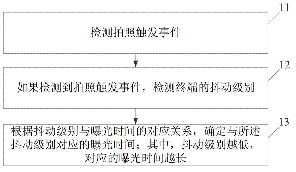
[0113] figure 1 It is a flow chart of the exposure time control method provided in Embodiment 1 of the present invention, and the process includes:
[0114] Step 11: Detect the camera trigger event.
[0115] In this step, the photographing trigger event may be to trigger a physical button with a shutter function, or to click a soft button with a shutter function on the touch screen.
[0116] Step 12: If a camera trigger event is detected, detect the shaking level of the terminal.
[0117] Step 13: Determine the exposure time corresponding to the shake level according to the correspondence between the shake level and the exposure time; wherein, the lower the shake level is, the longer the corresponding exposure time is.
[0118] In this step, the jitter level reflects the user's jitter degree, and the higher the jitter level, the higher the reflected jitter degree.
[0119] The corresponding relationship between the shake level and the exposure time is pre-set. Different sha...
Embodiment 2
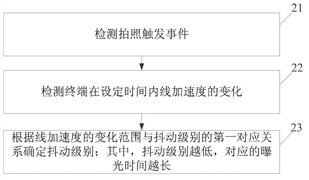
[0122] figure 2 It is a flow chart of the control method of the exposure time provided in Embodiment 2 of the present invention, and the process includes:
[0123] Step 21: Detect a camera trigger event.
[0124] In this step, the photographing trigger event may be to trigger a physical button with a shutter function, or to click a soft button with a shutter function on the touch screen.
[0125] Step 22: Detect changes in linear acceleration of the terminal within a set time.
[0126] Optionally, in this step, detecting the change of the linear acceleration of the terminal within the set time can be realized in the following manner: at each moment within the set time, respectively detect the linear acceleration components of the terminal in each set direction, and calculate each Set the absolute value of the difference between the linear acceleration component at this moment and the linear acceleration component at the previous moment, and add the absolute values of each...
Embodiment 3
[0140] Figure 5 It is a flow chart of the control method of the exposure time provided by Embodiment 3 of the present invention, and the process includes:
[0141] Step 51: Detect a photo-taking trigger event.
[0142] In this step, the photographing trigger event may be to trigger a physical button with a shutter function, or to click a soft button with a shutter function on the touch screen.
[0143] Step 52: Detect changes in angular acceleration of the terminal within a set time.
[0144] Optionally, in this step, detecting the change of the angular acceleration of the terminal within the set time can be achieved by the following method: at each moment within the set time, respectively detect the angular acceleration components of the terminal in each set direction, and calculate each Set the absolute value of the difference between the angular acceleration component at this moment and the angular acceleration component at the previous moment, and add the absolute value...
PUM
 Abstract
Description
Claims
Application Information