
Power source switching circuit, earphone wire distributing device, multiple-wire earphone power supplying device and control method

A technology of power switching and headphone splitter, applied in transducer circuits, earpiece/headphone accessories, electrical components, etc., can solve problems such as inability to drive channels and low maximum power

Active Publication Date: 2013-04-17
XIAOMI INC
View PDF2 Cites 0 Cited by
  • Summary
  • Abstract
  • Description
  • Claims
  • Application Information

AI Technical Summary

Problems solved by technology

[0004] The inventors of the present invention have found that since the driving power provided by the terminal is fixed, when multiple earphones are connected through an earphone splitter, the maximum power available for each earphone is reduced. When driving a high-power earphone, such as a bass earphone, it may will not be able to drive the channel because the maximum power allocated is too small

Method used


Image

  • Power source switching circuit, earphone wire distributing device, multiple-wire earphone power supplying device and control method
  • Power source switching circuit, earphone wire distributing device, multiple-wire earphone power supplying device and control method
  • Power source switching circuit, earphone wire distributing device, multiple-wire earphone power supplying device and control method

Examples


Embodiment Construction

[0029] The following will clearly and completely describe the technical solutions in the embodiments of the present invention with reference to the accompanying drawings in the embodiments of the present invention. Obviously, the described embodiments are only some, not all, embodiments of the present invention. All other embodiments obtained by those skilled in the art based on the embodiments of the present invention belong to the protection scope of the present invention.

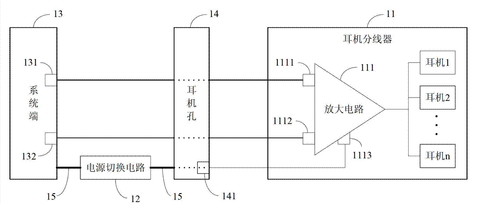
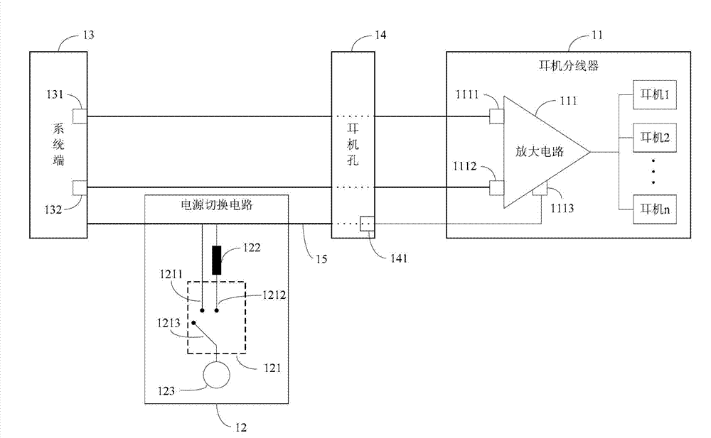
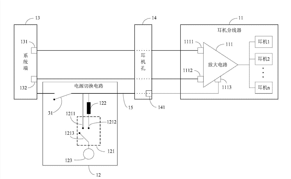
[0030] Please refer to the attached figure 1 , is a schematic structural diagram of a multi-line earphone power supply device provided by an embodiment of the present invention. For ease of description, only parts related to the embodiments of the present invention are shown. attached figure 1 The example multi-wire earphone power supply device can be used in mobile phones, MP3 players and other terminals with sound output functions, and the attached figure 1 The exemplary multi-line earphone power su...


PUM


Abstract

The embodiment of the invention provides a power source switching circuit, an earphone wire distributing device, a multiple-wire earphone power supplying device and a control method, aiming at providing sufficient power for the earphone wire distributing device to drive a plurality of earphones connected with the earphone wire distributing device. The device comprises the earphone wire distributing device and the power source switching circuit, wherein the earphone wire distributing device comprises an amplifying circuit, the amplifying circuit is used for receiving the power source switched by the power source switching circuit to drive the earphones connected with the earphone wire distributing device, an electroacoustic signal input and output end is directly communicated with a signal line which is positioned between an earphone hole and a system terminal, and the power source switching circuit is used for inputting the power source into the driving input end of the amplifying circuit through the electroacoustic signal input and output end by switching. The multiple-wire earphone power supplying device provided by the invention has the advantages that the sufficient driving power can be provided for the earphones, even if the earphone wire distributing device is connected with one large-power earphone or a plurality of large-power earphones; and the requirements of power driving of the large-power earphones can be met.

Description

technical field [0001] The invention relates to the communication field, in particular to a power switching circuit, an earphone splitter, a multi-line earphone power supply device and a control method. Background technique [0002] Headphone splitter is a relatively common peripheral for mobile phones, MP3 players and other terminals with sound output functions. Its function is to divide the left channel of these terminals into multiple left channels, and divide the right channel of these terminals into multiple channels. For multiple right channels so multiple people can share the same music and more. [0003] The headphone splitter provided by the prior art is simply physically connected to the terminal, and the left and right sound channels rely on the terminal to provide the required driving power; for each headphone connected to the headphone splitter, the left and right sound channels are provided by the equal distribution terminal. drive power to work. [0004] The...

Claims


Application Information

Patent Timeline
IPC IPC(8): H04R3/00H04R1/10
Inventor 孙伟文红张鹏飞
Owner XIAOMI INC
Learn More