
Additive manufacturing management of large part build mass

A technique for additive manufacturing, parts, applied in the field of laser construction

Active Publication Date: 2013-04-24
UNITED TECH CORP
View PDF8 Cites 21 Cited by
  • Summary
  • Abstract
  • Description
  • Claims
  • Application Information

AI Technical Summary

Problems solved by technology

However, as capacity increases and larger parts are manufactured, excess powder metal can become an important consideration in both part manufacturability and economic viability

Method used


Image

  • Additive manufacturing management of large part build mass
  • Additive manufacturing management of large part build mass
  • Additive manufacturing management of large part build mass

Examples


Embodiment Construction

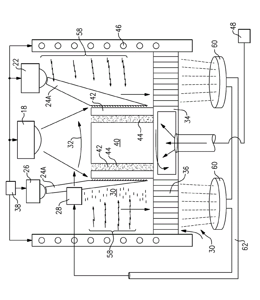
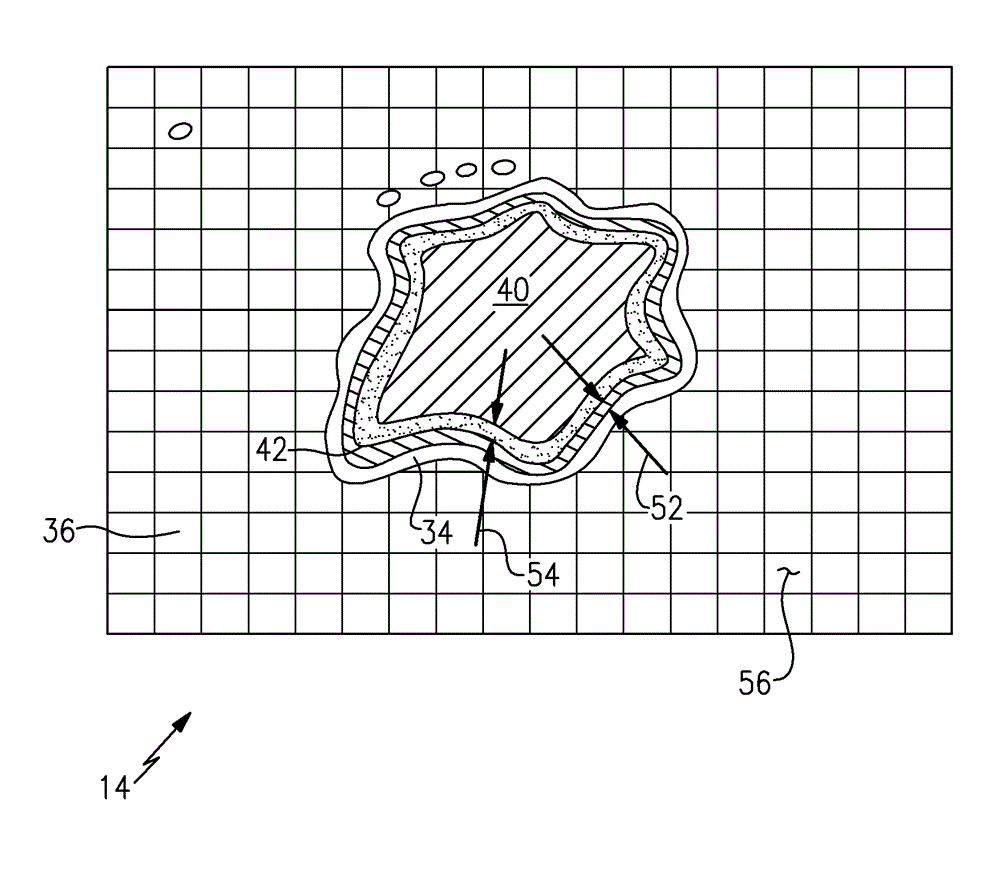
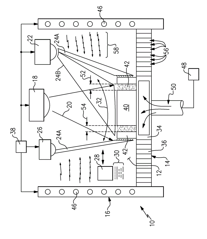
[0029] Referring to FIG. 1 , an additive manufacturing machine 10 includes a workspace 12 that supports an energy emitting device 18 and a substrate 14 on which a part 40 is supported during manufacture. In this example, energy emitting device 18 emits laser beam 20 that melts material 30 deposited by material applicator 28 . An exemplary material 30 is a metal powder that is applied in layers on the substrate 14 and subsequent layers are applied to produce the desired configuration of the part 40 . The laser beam 20 directs energy that melts the powder material into a configuration that forms the desired part dimensions.

[0030] The additive manufacturing process employs a material 30 that is applied to form multiple layers on top of the substrate 14 . Selective portions of the layer are subsequently melted by the energy emitted from the laser beam 20 . Energy focused on the top layer of part 40 generates the desired heat to melt portions of the powder metal. Heat conduct...


PUM


Abstract

An additive manufacturing machine includes a base plate for supporting fabrication of a desired part geometry. The base plate includes a support portion defined based on the desired part geometry and an open region that includes a plurality of openings surrounding the support portion. A material applicator deposits material onto the base plate and an energy directing device directs energy to form the deposited material into a desired part geometry. The additive manufacturing machine manages large amounts of material required for fabricating the part by defining a boundary surrounding a periphery of a desired part geometry and forming a retaining wall along the defined boundary and the desired part geometry to retain excess material between the formed wall and the part. Excess material outside of the retaining wall falls through the open area below the base plate and is reclaimed for reuse.

Description

[0001] Cross References to Related Applications [0002] This application claims priority to US Provisional Application No. 61 / 549,868, filed October 21, 2011. technical field [0003] The present disclosure generally relates to laser configurations for additive manufacturing machines and processes. More specifically, the present disclosure relates to configurations for relieving stress within a part during creation within an additively manufactured assembly. Background technique [0004] Typical fabrication methods include various methods of removing material from the starting blank to form the desired finished part shape. Such methods employ cutting tools to remove material to form holes, surfaces, general shapes, etc., by cutting material from a starting material. Such subtractive manufacturing methods place physical constraints on the final shape of the finished part. Additive manufacturing methods form the desired part shape by adding one layer at a time, thus provid...

Claims


Application Information

Patent Timeline
IPC IPC(8): B22F3/105
CPCB29C64/153B33Y30/00B33Y10/00B29C64/188Y02P10/25B22F10/34B22F10/47B22F12/41B22F10/73
Inventor J.J.克雷姆斯J.D.海恩斯Y.高D.E.马特茨克J.G.兰道
Owner UNITED TECH CORP
Learn More