Multichannel hydraulic swivel joint

A rotary joint, multi-channel technology, applied in the direction of load hanging components, earthmoving machines/shovels, construction, etc., can solve the influence of rotary body and rotary shaft, pipeline and line interference, easy oil leakage of rotary joints, etc. problems, to achieve the effect of improving applicability, reducing labor intensity, and ensuring performance

Inactive Publication Date: 2013-04-24
JIANGSU CHANGLING HYDRAULIC CO LTD
View PDF0 Cites 0 Cited by
  • Summary
  • Abstract
  • Description
  • Claims
  • Application Information

AI Technical Summary

Problems solved by technology

[0003] However, after the conventional multi-channel hydraulic rotary joints connect the hydraulic lines and circuits of the fixed part and the rotating part in the hydraulic system and the circuit, the fixed part and the rotating part cannot be rotated 360° relative to each other, which will cause interference between the pipes and lines, and oil The road and the bottom are not smooth, and the oil circuits and circuits are connected in series
[0004] Moreover, the sealing performance between the rotary joint and the outside world in the past is poor, and the dust from the outside is easy to drill into the rotary joint, which affects the performance of the rotary joint, and the oil in the rotary joint is also easy to leak out, which is difficult for the rotary body and the rotary shaft in the rotary joint. The rotation also has an impact, requiring frequent oiling, which increases the labor intensity of the workers

Method used


Image

  • Multichannel hydraulic swivel joint
  • Multichannel hydraulic swivel joint
  • Multichannel hydraulic swivel joint

Examples


Embodiment Construction

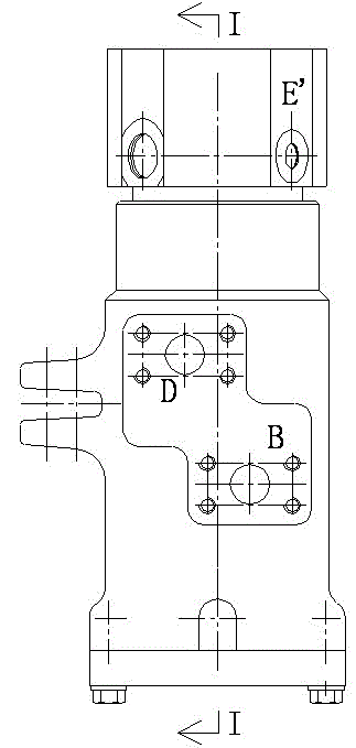
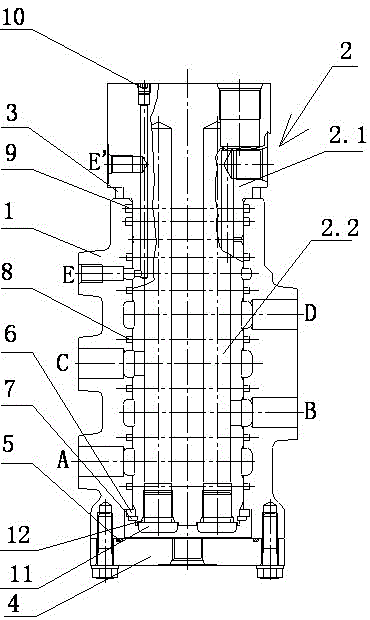
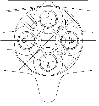
[0018] see Figure 1 to Figure 5 , the present invention relates to a multi-channel hydraulic rotary joint, including a rotary body 1 and a rotary shaft 2, the rotary shaft 2 is composed of an upper pipeline connection section 2.1 and a lower installation section 2.2, and the lower installation section 2.2 is formed from the rotary body 1 The upper end of the rotary body 1 is axially inserted into the rotary body 1, the lower end of the rotary body 1 is lower than the horizontal position of the lower end of the lower installation section 2.2, the upper pipeline connection section 2.1 is exposed to the rotary body 1, and the upper end of the rotary body 1 is connected to the A water seal ring 3 is provided between the rotating shafts 2 to prevent gas leakage or entry. The lower end of the rotary body 1 is provided with an end cover 4, and the end cover 4 is fixed to the lower end of the rotary body 1 by bolts. An O-ring I5 is provided between the lower end of the rotary body 1 ...


PUM


Abstract

The invention relates to a multichannel hydraulic swivel joint which comprises a swiveling body (1) and a swiveling shaft (2). The multichannel hydraulic swivel joint is characterized in that the swiveling shaft (2) is composed of an upper pipeline connecting part (2.1) and a lower installation part (2.2), four main oil way holes and a low pressure oil way hole are formed in the axial direction of the swiveling shaft (2), a scraper seal (9) is arranged in an annular groove positioned between the swiveling body (1) and the lower installation part (2.2), an upper lip mouth (9.1) and a lower lip mouth (9.1) are formed in one side where the scraper seal (9) contacts with the swiveling shaft (2), and thus double lip mouths are formed. The upper lip mouth (9.1) and the lower lip mouth (9.1) are both attached tightly to the outer wall of the swiveling shaft (2). According to the multichannel hydraulic swivel joint, dust is not easy to get in the swivel joint, oil is not easy to leak, and fixed parts and swiveling parts of a hydraulic system and circuits are enabled to rotate 360 degrees relatively. In addition, oil ways are unblocked from top to bottom, and each oil way and the circuits are not connected in series.

Description

technical field [0001] The invention relates to a multi-channel hydraulic rotary joint, which is mainly used in the hydraulic systems of large-tonnage excavators, cranes, graders, tower cranes and other machinery. A connecting piece for a circuit belongs to the technical field of engineering machinery. Background technique [0002] For hydraulic excavators, cranes, loaders, etc., the upper and lower parts need to be rotated, so there is a problem of connecting the oil circuit and the circuit between the rotating part and the fixed part. The multi-channel hydraulic rotary joint is composed of a rotary body, a rotary shaft and a cover. When in use, the revolving body is fixed to the revolving lower platform of hydraulic excavators and cranes, and the mounting plate on the revolving shaft is connected with the slewing support on the revolving upper platform. Hydraulic rubber hoses and wires are respectively installed on the oil ports and lines of the rotary body and the rotar...

Claims


Application Information

Patent Timeline
Patent Type & Authority Applications(China)
IPC IPC(8): F16L39/06E02F9/22B66C13/12
Inventor 夏泽民张爱军陈酉冰潘逸明高海波朱江华
Owner JIANGSU CHANGLING HYDRAULIC CO LTD
Why Eureka
Try Eureka