
Leaking stoppage device of pipe hole leakage points

A leakage point and leak stopper technology, applied in the direction of pipe components, pipes/pipe joints/fittings, mechanical equipment, etc., can solve the problems of difficult to fill leaks, ineffective plugging of leaks, damage to sealing materials, etc., to achieve Efficient use, great practical value, and the effect of civilized operation

Inactive Publication Date: 2013-04-24
TIANJIN ZHUODA PIPELINE MACHINERY MFG
View PDF4 Cites 20 Cited by
  • Summary
  • Abstract
  • Description
  • Claims
  • Application Information

AI Technical Summary

Problems solved by technology

For example: wooden wedges, copper, aluminum, and lead sheets are manually riveted to temporarily plug leaks. When the hole is large, the wooden wedge enters a part of the pipeline, which affects the future passage of the pipeline. When the hole is small, it is difficult for the wooden wedge to fill the leak. Operation method In case of high-pressure pipelines, there is no local forced plugging tool, and the method of manual riveting with wooden wedges, copper, aluminum, and lead sheets cannot effectively block the leak point; or directly use steel tiles to press rubber sheets for manual plugging , and then weld the steel tiles on the pipeline
[0003] The above plugging method is a common basic method, but there is no special plugging tool for this method at present. Because there is only a method without special tools, there are problems such as leak plugging that cannot be welded strictly and steel tiles that can be welded, and heat conduction will damage the sealing material. The problem

Method used


Image

  • Leaking stoppage device of pipe hole leakage points
  • Leaking stoppage device of pipe hole leakage points
  • Leaking stoppage device of pipe hole leakage points

Examples


Embodiment Construction

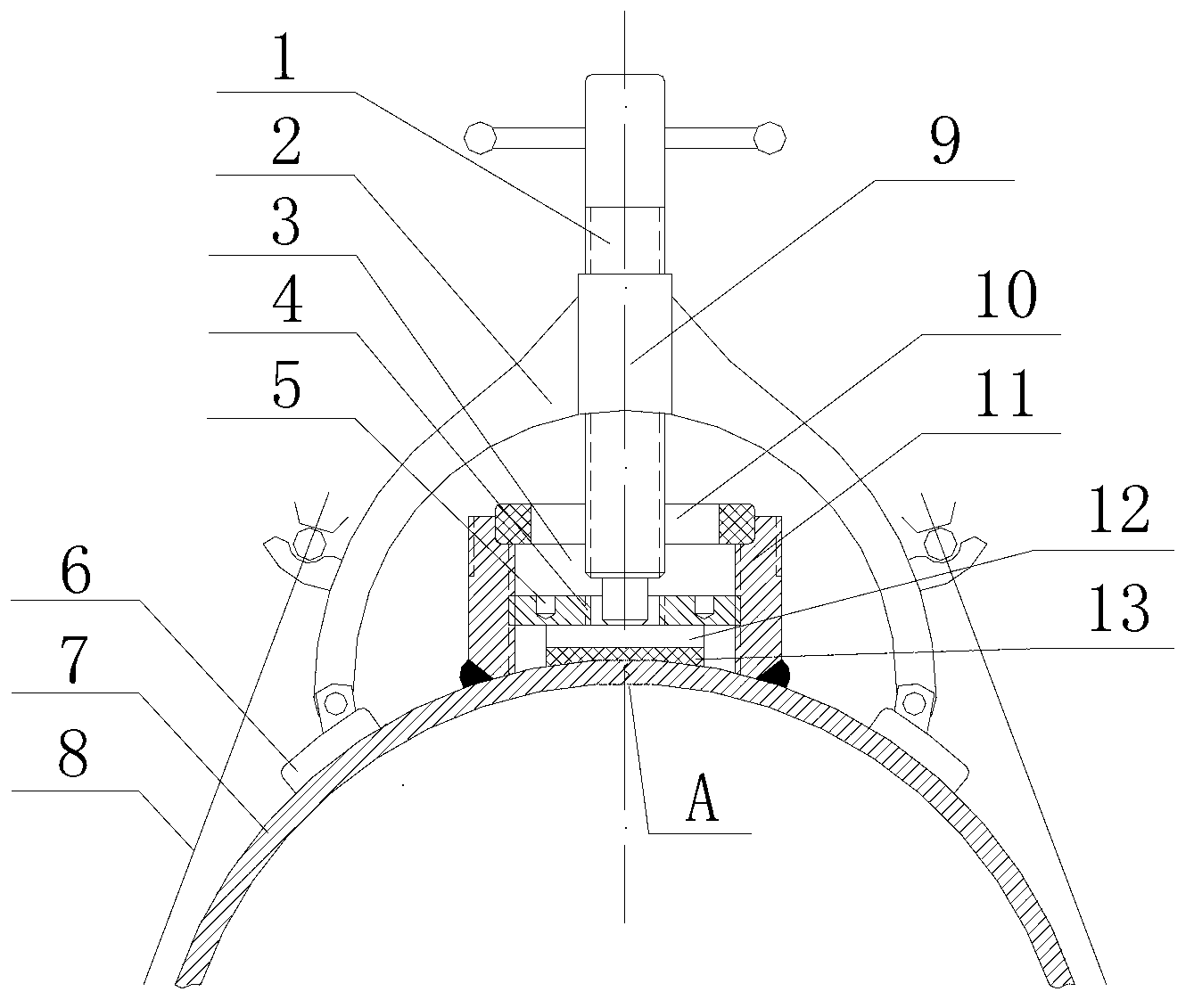
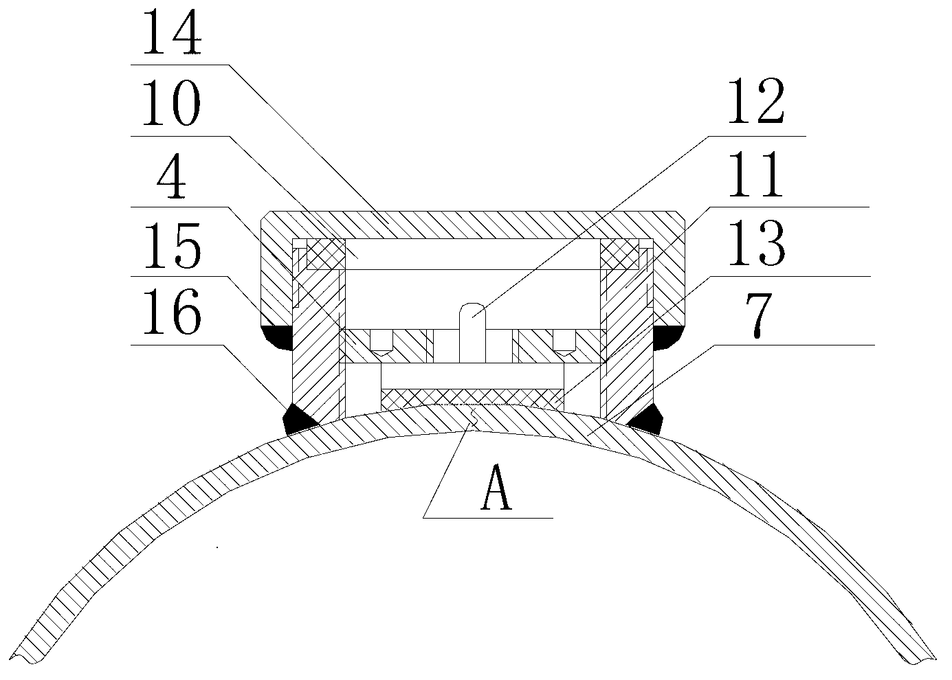
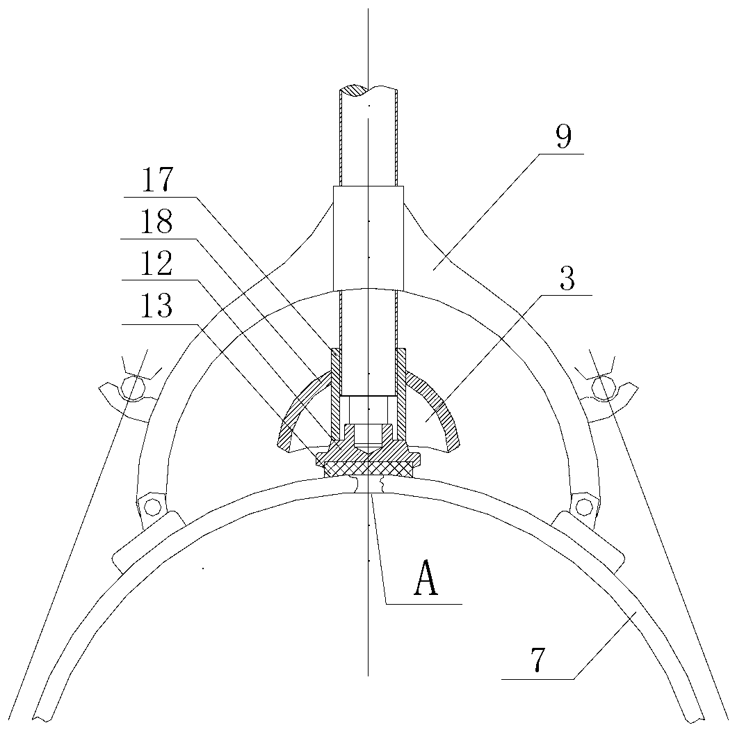
[0019] The leak plugging device for the leakage point of the pipeline hole of the present invention is composed of a fixing frame assembly 9 and a plugging body assembly 3 and the like. Among them: the fixed frame assembly is supported by two points of the arc bracket 2, the detachable tension chain 8 used to fix the arc bracket on the pipeline 7 to be plugged, and rotated in the center of the arc bracket, the axis is vertical It is composed of a lead screw 1 at the center of the pipeline to be plugged; the plugging body assembly includes a plugging body used to connect with the pipeline to be plugged, a compression part that is fixedly connected with the plugging body and has a central hole, and The sealing assembly compressed and fixed by the compressed part and a cover plug used for closing the leakage blocking body. The bottom of the sealing assembly in the plugging body assembly is a flexible sealing gasket 13, and the upper part is a metal pressing bracket 12. The flexi...


PUM


Abstract

The invention relates to a leaking stoppage device of pipe hole leakage points. The leaking stoppage device comprises a fixing support assembly and a leaking stoppage body assembly and is characterized in that the fixing support assembly is composed of an arc support with two supporting points, a dismountable tensioning chain capable of fixing the arc support on a plugged pipe and a lead screw which is screwed in the center of the arc support and provided with an axis vertical to a center of the plugged pipe. The leaking stoppage body assembly comprises a leaking stoppage body connected with a pipe needing plugging, a pressing component which is fixedly connected with the leaking stoppage body and provided with a central hole, a sealing assembly which is fixedly pressed by the pressing component and a cover plug used for sealing the leaking stoppage body. The bottom of the sealing assembly in the leaking stoppage body assembly is flexible sealing gasket, and the upper portion is a metal compact support. The leaking stoppage device firstly plugs a leaked combustible medium, then uses fire to weld, and is specially used for leaking stoppage emergency of a steel pipe. The leaking stoppage device is an indispensable and necessary urgent repairing tool for repairing flammable and combustible pipes for oil and gas.

Description

【Technical field】 [0001] The invention relates to the sealing construction technology of petroleum, chemical industry, natural gas and other transmission pipelines, in particular to a special appliance for plugging and emergency rescue of high-pressure and high-temperature pipelines, in particular to a leakage plugging device for pipeline hole leakage. 【Background technique】 [0002] In the prior art, the non-stop leak plugging construction for the inflammable and explosive pipelines such as petroleum, chemical industry, natural gas, etc. that occurs when transporting media is usually only a manual operation. For example, using soft metal, riveting and manual extrusion of steel tiles filled with rubber sheets, and then welding the steel tiles for plugging. For example: wooden wedges, copper, aluminum, and lead sheets are manually riveted to temporarily plug leaks. When the hole is large, the wooden wedge enters a part of the pipeline, which affects the future passage of the ...

Claims


Application Information

Patent Timeline
Patent Type & Authority Applications(China)
IPC IPC(8): F16L55/17
Inventor 马斌马耀马箭甄翔张海潮景德洲王兴辉
Owner TIANJIN ZHUODA PIPELINE MACHINERY MFG
Learn More