
Ferrite Cores and Transformers

A technology of ferrite iron and transformers, applied in transformer/inductor parts, inductance/transformer/magnet manufacturing, magnetic objects, etc., can solve the problems of increasing opportunities for use and increasing temperature rise

Active Publication Date: 2016-05-18
TDK CORPARATION
View PDF7 Cites 0 Cited by
  • Summary
  • Abstract
  • Description
  • Claims
  • Application Information

AI Technical Summary

Problems solved by technology

Under such circumstances, the temperature rise caused by the heat generation of the iron core tends to increase, and the chances of using the iron core in an environment that is strict with temperature rise increase.

Method used


Image

  • Ferrite Cores and Transformers
  • Ferrite Cores and Transformers
  • Ferrite Cores and Transformers

Examples


Embodiment 1~28

[0076] Each component raw material was weighed so that it might become the composition shown in Table 1, and it wet-mixed using the ball mill. After the raw material mixture is dried, it is calcined at a temperature of about 900° C. in air. The obtained calcined powder was charged into a ball mill, and wet pulverization was performed for 3 hours until the desired particle size was obtained.

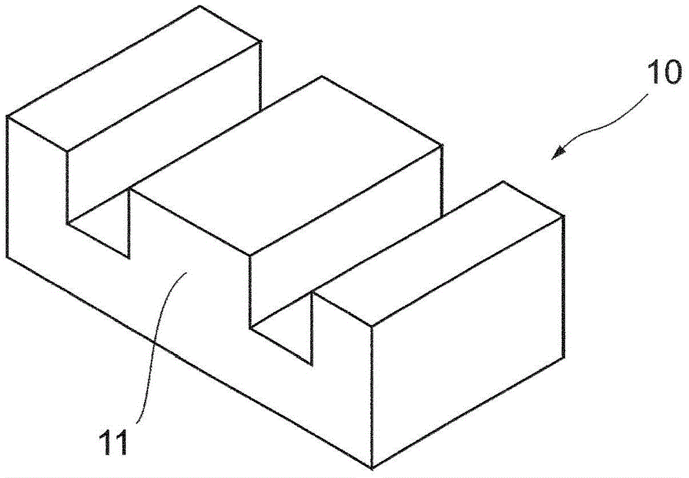
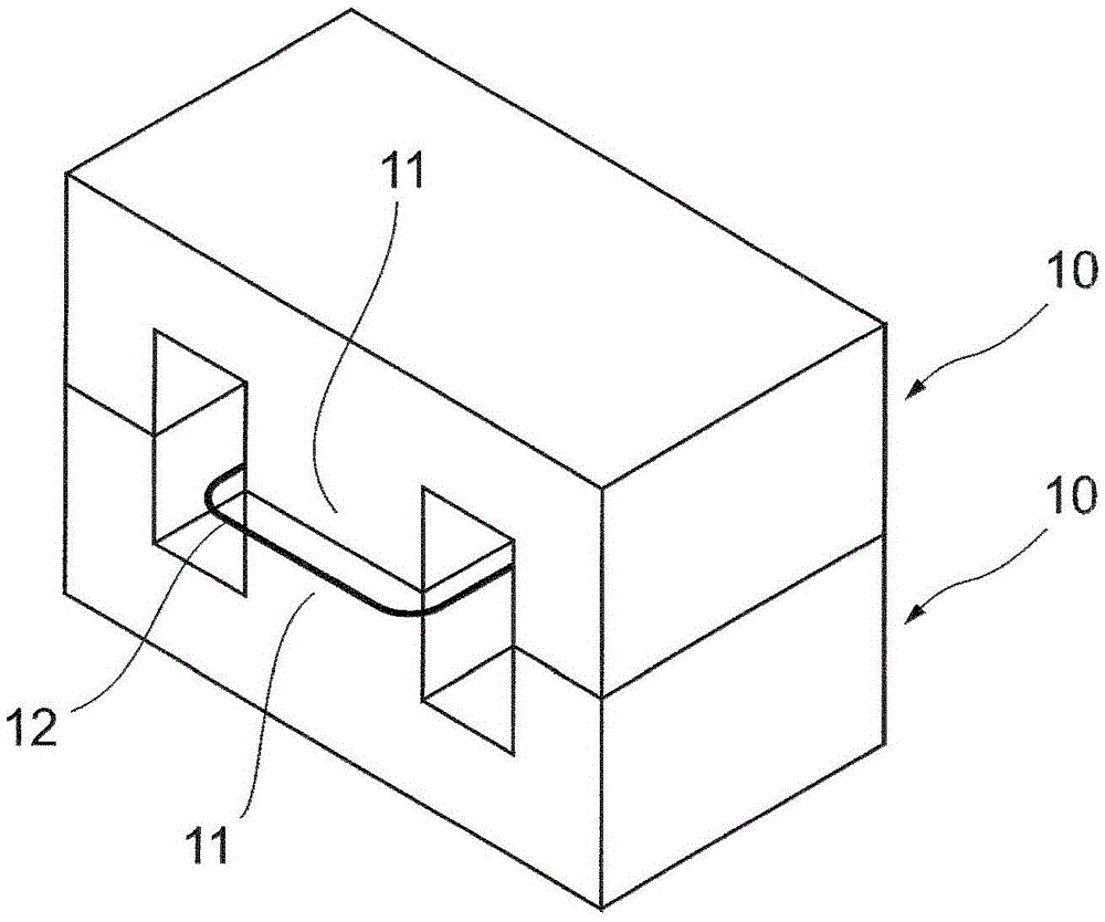
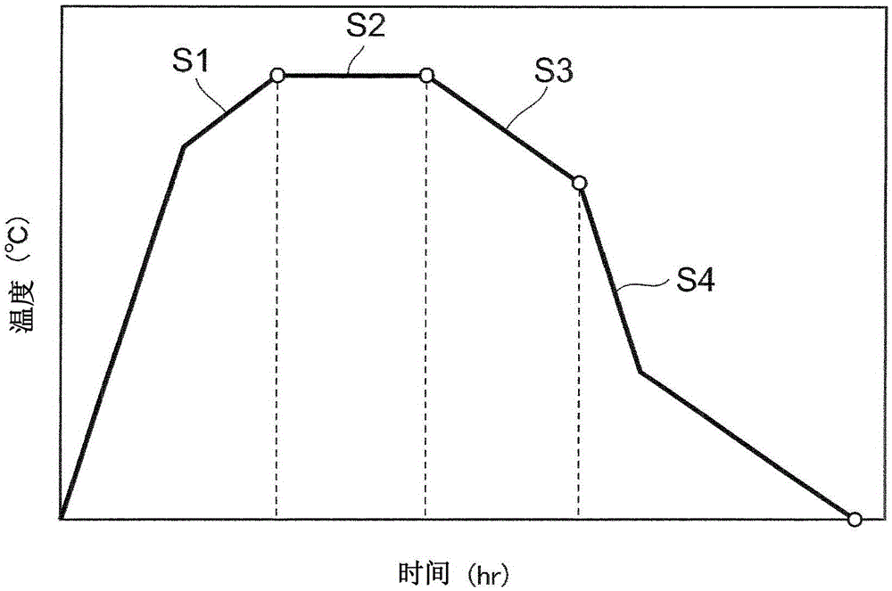
[0077] The pulverized powder thus obtained was dried, and after adding 0.8 parts by mass of polyvinyl alcohol to 100 parts by mass of the pulverized powder for granulation, the resulting mixture was press-molded at a pressure of about 150 MPa to obtain E Font shape. The molded body was mainly fired within the range of firing conditions shown below to obtain a plurality of E-shaped ferrite cores. In this main firing step, the holding temperature is 1250 to 1350°C, and the slow cooling end temperature is set to 900 to 1150°C. After completion of the slow cooling process S3, the atmospher...


PUM


Abstract

The present invention provides a ferrite core and a transformer which can sufficiently suppress core temperature increase in a condition of continuous excitation. The ferrite core provided by the invention comprises Fe, Mn, Zn and Co. For x which is defined in a formula (1), when the x of the surface part with depth smaller than 1.5mm to the surface of sintered member is x(o), and the x of the inner part with depth larger than 2.5mm to the surface of the sintered member is x(i), [x(o)-x(i)] which represents difference between the inner part and the outer part of the sintered member satisfies -0.0015<=[x(o)-x(i)]<=0.0005, x=(Fe<2+>-Co<3+>-Mn<3+>) / (Fe+Mn+Zn+Co)...formula (1), wherein, the unit of (Fe<2+>-Co<3+>-Mn<3+>) in the formula (1) is wt%, and the unit of (Fe+Mn+Zn+Co) is also wt%.

Description

technical field [0001] The present invention relates to a ferrite core containing Fe, Mn, Zn and Co. Background technique [0002] A ferrite sintered body is used as an iron core material for a power supply transformer or the like. The ferrite sintered body forming the core is called a ferrite core, and MnZn-based ferrite containing Mn and Zn is widely used. From the viewpoint of reducing the calorific value of the iron core when the instrument is used, it is required that the value of the core loss of the ferrite iron core be small in the temperature range of use. [0003] In recent years, electronic devices and power supplies have been gradually miniaturized, and the densification of components in the electronic devices has also been progressed. Under such circumstances, the temperature rise due to heat generation of the iron core tends to increase, and the chances of the iron core being used in an environment that is critical to temperature rise increase. Therefore, it...

Claims


Application Information

Patent Timeline
Patent Type & Authority Patents(China)
IPC IPC(8): H01F27/255H01F1/36H01F41/02
CPCC04B35/2608C04B35/265C04B35/2658C04B2235/3274C04B2235/3284H01F1/344
Inventor 安原克志须佐昌司森健太郎蒲生正浩高川建弥
Owner TDK CORPARATION
Learn More