Slider for zipper and zipper having same

A technology for zippers and sliders, applied in the field of zippers, which can solve problems such as peeling, harshness, scratches on the pull piece or slider body, and achieve the effect of improving strength

Active Publication Date: 2015-07-29
YKK CORP
View PDF4 Cites 4 Cited by
  • Summary
  • Abstract
  • Description
  • Claims
  • Application Information

AI Technical Summary

Problems solved by technology

The reason is that there may be a harsh sound due to the swing of the pull tab and the collision with the slider body.
In addition, scratches and paint peeling are caused on the pull tab or the slider body due to swinging of the pull tab and collision with the slider body.

Method used


Image

  • Slider for zipper and zipper having same
  • Slider for zipper and zipper having same
  • Slider for zipper and zipper having same

Examples


no. 1 approach

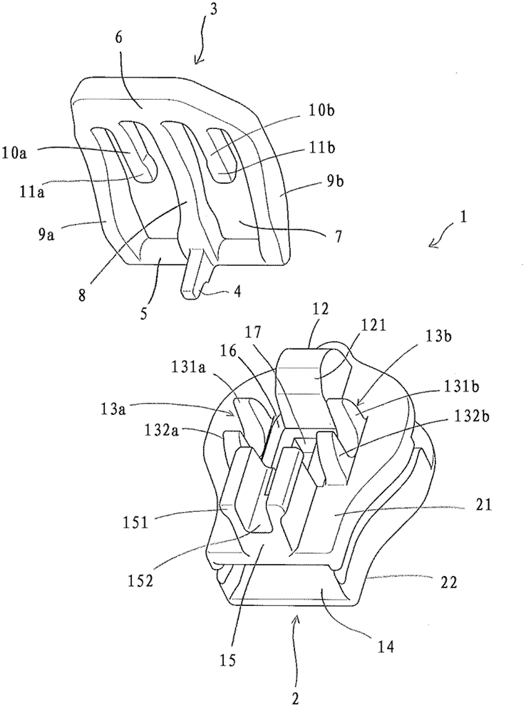
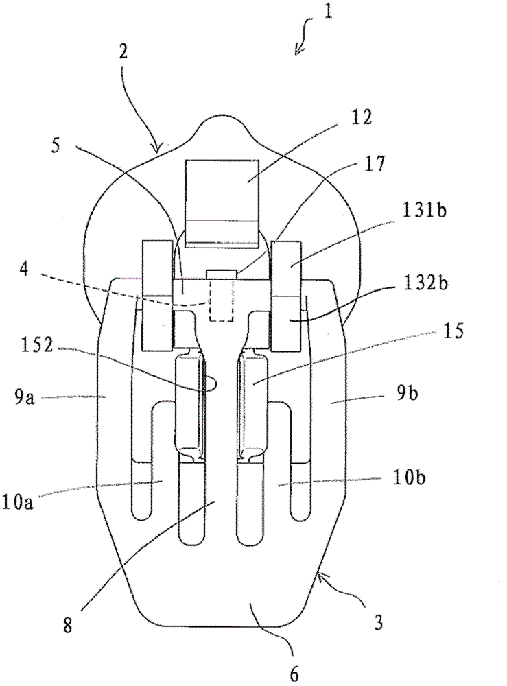
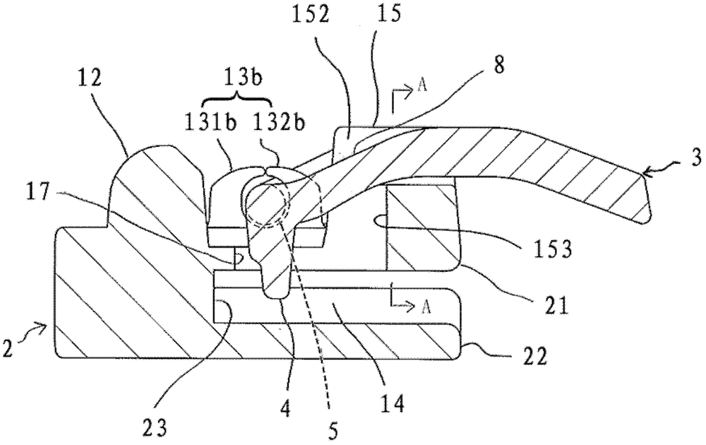
[0091] Figure 1 to Figure 5 It is a figure which shows the slider which concerns on 1st Embodiment of this invention. figure 1 It is an exploded perspective view of the slider according to the first embodiment of the present invention; figure 2 is a top view of the slider according to the first embodiment of the present invention, wherein the slider is in the first position; image 3 is a side sectional view of the slider according to the first embodiment of the present invention, wherein the slider is in the first position; Figure 4 for along image 3 A cross-sectional view of line A-A in ; Figure 5 It is a side sectional view of the slider which concerns on 1st Embodiment of this invention, wherein the handle is in a 2nd posture.

[0092] Such as figure 1 As shown, the slider 1 has a slider body 2 and a pull piece 3 , and the pull piece 3 can rotate between a first posture laid down on the slider body 2 and a second posture erected from the slider body 2 . In this ...

no. 2 approach

[0103] Figure 6 ~ Figure 7 It is a figure which shows the slider of 2nd Embodiment of this invention. Figure 6 It is a top view of the slider according to the second embodiment of the present invention, wherein the slider is in the first position; Figure 7 It is a side sectional view of the slider which concerns on the 2nd Embodiment of this invention, wherein the handle is in a 2nd posture. In addition, in the description of the present embodiment, the same reference numerals are attached to the same or corresponding parts as those of the first embodiment, and the description of the parts will be omitted.

[0104] Such as Figure 6 as well as Figure 7 As shown, compared with the first embodiment, in the second embodiment, the rod and the first groove for accommodating the rod are not formed. And, instead of being provided with one first column portion in the first embodiment, in the second embodiment, on the front side of the slider body 2, there are pullers along the...

no. 3 approach

[0108] Figure 8 ~ Figure 9 It is a figure which shows the slider which concerns on 3rd Embodiment of this invention. Figure 8 It is a top view of the slider according to the third embodiment of the present invention, wherein the slider is in the first position; Figure 9 It is a side sectional view of the slider which concerns on the 3rd Embodiment of this invention, wherein the handle is in a 2nd posture. In addition, in the description of the present embodiment, the same reference numerals are attached to the same or corresponding parts as those of the first embodiment, and the description of the parts will be omitted.

[0109] Such as Figure 8 as well as Figure 9 As shown, compared with the first embodiment, in this third embodiment, no recess is formed, but between the pair of left and right support parts 13a, 13b, the upper plate 21 of the slider body 2 is penetrated in the vertical direction. In such a manner, the hole portion 17 communicating with the element pa...


PUM


Abstract

There is provided a slider for slide fastener, including a slider body and a pull tab. A pair of supporting parts rotatably supporting the pull tab are provided on an upper surface of the slider body, and a claw for snapping elements of the slide fastener is provided on the pull tab. The pull tab is rotatable between a first posture in which the pull tab is placed down on the slider body and a second posture in which the pull tab is erected from the slider body. A stop member is provided on at least one of the slider body and the pull tab. The stop member limits the pull tab in an erect position of the second posture such that a front end of the claw is located within a protection space.

Description

technical field [0001] The invention relates to the technical field of zippers, in particular to a slider for a zipper and a zipper with the slider. Background technique [0002] With regard to the slide fastener installed on clothes, shoes, etc., when the wearer of the clothes or shoes moves, it is necessary to prevent the slider of the slide fastener from swinging wildly. The reason for this is that there is a possibility of making a harsh sound due to the swing of the pull tab and the collision with the slider body. In addition, since the pull tab swings and collides with the slider body, scratches and paint peeling are caused on the handle or the slider body. [0003] In order to solve the above-mentioned problems, Patent Document 1 proposes a slide fastener in which a slider has a slider body and a handle rotatably supported by the slider body. The handle has a window and left and right locking pieces protruding from the edge of the window. The slider body has a firs...

Claims


Application Information

Patent Timeline
Patent Type & Authority Patents(China)
IPC IPC(8): A44B19/26
CPCY10T24/2586A44B19/305A44B19/262Y10T24/2568Y10T24/2566A44B19/30A44B19/303
Inventor 松岛秀幸
Owner YKK CORP
Why Eureka
Try Eureka