
A beam with rolling and sliding rails

A beam and guide rail technology, applied in milling machine equipment, metal processing equipment, large fixed members, etc., can solve the problems of inefficient rough milling, poor machining accuracy, and difficult to guarantee machining accuracy.

Inactive Publication Date: 2015-08-26
金正淼
View PDF8 Cites 0 Cited by
  • Summary
  • Abstract
  • Description
  • Claims
  • Application Information

AI Technical Summary

Problems solved by technology

[0003] The two sets of load-carrying rails of the one-to-two crossbeam in the prior art are all one kind, that is, either the hard rail structure that is all sliding is called sliding hard rail, or the line rail structure that is all rolling is called rolling line rail; The rail is suitable for bearing the strong impact and vibration produced by heavy-duty rough milling, and the rolling line rail is suitable for high-speed precision fine milling. Since the two sets of bearing rails for the same beam are one type, it is difficult for one-to-two CNC milling machines to meet the requirements of one-time clamping. Rough and fine compatible processing requirements, that is, rough milling is efficient, fine milling is not precise, and fine milling is precise, but rough milling is not efficient. It is used for precision fine milling; for efficient heavy-duty rough milling, the one-to-two CNC milling machine with sliding hard rails is only used for heavy-duty rough milling. In addition, the workpiece after heavy-duty rough milling must be moved to the precision machining After the machine tool is clamped for the second time, the finishing milling process is performed. Repeatedly moving and clamping in this way is labor-intensive and time-consuming, resulting in high processing costs, low efficiency, and difficult to guarantee processing accuracy. The problems and deficiencies of high ranking, low efficiency and poor machining accuracy

Method used


Image

  • A beam with rolling and sliding rails
  • A beam with rolling and sliding rails

Examples


Embodiment Construction

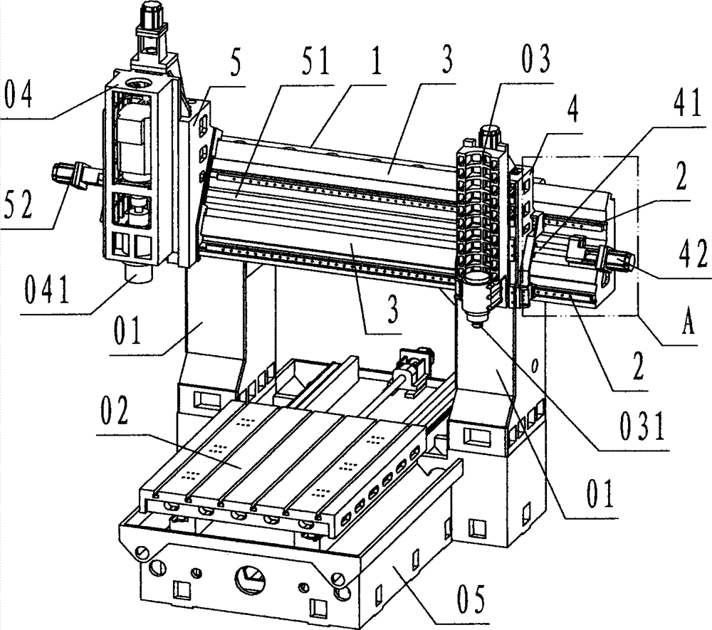
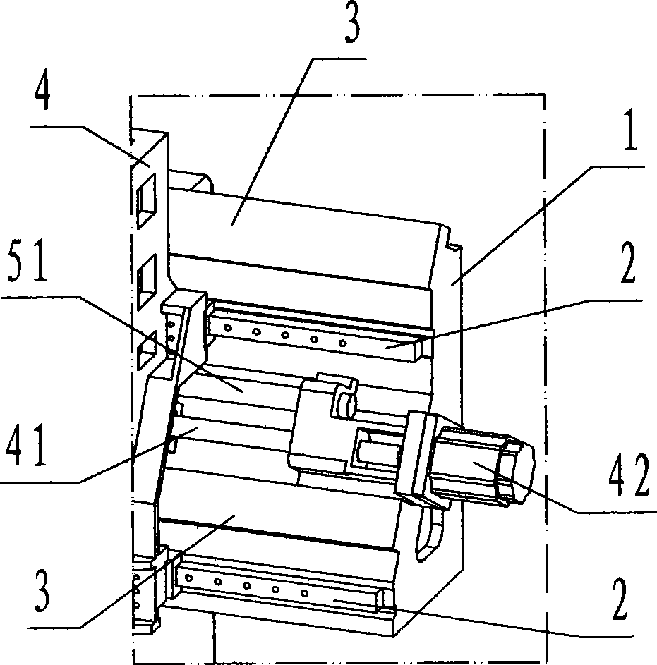
[0018] refer to Figure 1 ~ Figure 2 , a crossbeam provided with rolling and sliding guide rails according to the present invention includes a crossbeam 1, a rolling line rail 2 and a sliding hard rail 3, wherein: the crossbeam 1 is rectangular in main view, L-shaped in side view, The long block-shaped cast iron components horizontally fixed on the two columns 01 of the one-to-two CNC milling machine, and the middle and lower parts in front of the beam 1 are provided with two horizontal parallel grooves called line rail grooves;

[0019] The sliding hard rails 3 are two horizontally parallel rails with an inverted V-shaped cross-section arranged on the top of the crossbeam 1 and the front middle; The front left part of 1; the heavy-duty lateral motion device 5 is a device for undertaking the heavy-duty rough milling task for controlled lateral motion consisting of a heavy-duty vertical motion device 04 and a heavy-duty spindle motor 041; the heavy-duty lateral motion device 5 ...


PUM


Abstract

The invention discloses a beam with a rolling guide track and a sliding guid track. The beam with the rolling guide track and the sliding guid track comprises a beam (1), a rolling line track(2) and a sliding hard track (3). According to the beam with the rolling guide track and the sliding guid track, two guide tracks of the rolling line track and the sliding hard track are respectively arranged on the beam, when rough milling is carried out, a light-load transverse motion device is controlled to stay at a side and be static, a heavy-load X lead screw assembly and a heavy-load X servo motor are controlled to drag a heavy-load transverse motion device to carry out transverse motion target heavy-load rough milling along an axis X on the beam, when fine milling is carried out, the heavy-load transverse motion device is controlled to stay at the side and be static, a light-load X lead screw assembly and a light-load X servo motor are controlled to drag the light-load transverse motion device to carry out transverse motion target light-load fine milling along the axis X on the beam. The technical scheme is applied, a one-drag-two numerical control milling machine is capable of being through rough processing and fine processing by one-time clamping, and the aims that the rough processing and the fine processing are compatible, cost is lowered, efficiency is improved, and processing accuracy is improved are achieved.

Description

technical field [0001] The invention relates to a beam member of a numerically controlled milling machine, specifically referring to two sets of rolling and sliding guide rails provided on the beam of a numerically controlled milling machine, respectively bearing and dragging two sets for high-speed fine milling and heavy-duty rough milling A type of lateral movement device with a beam that has two guide rails for rolling and sliding. Background technique [0002] The CNC milling machine is composed of a three-axis three-dimensional Cartesian coordinate motion device in the X direction, Y direction, and Z direction. The beam is a component used by the CNC engraving and milling machine tool to carry and drag the lateral motion device for lateral movement, that is, the X direction. The so-called lateral motion device consists of Z direction Skateboard pair, Z-direction screw pair, Z-direction servo motor, and spindle motor; the beam of some CNC milling machines only carries an...

Claims


Application Information

Patent Timeline
Patent Type & Authority Patents(China)
IPC IPC(8): B23Q1/01B23Q1/48B23Q5/36B23Q5/40B23C1/08
Inventor 金正淼
Owner 金正淼
Learn More