
A CNC four-axis device

The technology of a shaft device and a rotating shaft is applied in the field of numerical control rotating shaft clamping device, which can solve the problems of low production efficiency, high processing cost, and high production cost of four-axis machining parts, and achieve the effect of improving efficiency and reducing cost.

Active Publication Date: 2015-11-25
宁波市凯博数控机械有限公司
View PDF8 Cites 0 Cited by
  • Summary
  • Abstract
  • Description
  • Claims
  • Application Information

AI Technical Summary

Problems solved by technology

[0002] The rotary cutting tools of ordinary CNC engraving and milling machine tools can only perform cutting motions along the XYZ three-axis, that is, three-axis motion processing; for workpieces that need to cooperate with cutting tools to revolve around the transverse axis parallel to the table and at the same time around the longitudinal direction perpendicular to the transverse axis The processing of the axis for rotating motion, that is, the workpiece processed by the four-axis motion, is referred to as the four-axis workpiece. In the prior art, the machining center with the five-axis motion is used to process the four-axis workpiece. General-purpose metal cutting processing equipment also has high processing costs. Using a five-axis machining center to process a large number of four-axis workpieces makes the production cost of four-axis workpieces high and the production efficiency is low. Therefore, the existing technology has high costs, Low efficiency problems and deficiencies

Method used


Image

  • A CNC four-axis device
  • A CNC four-axis device

Examples


Embodiment Construction

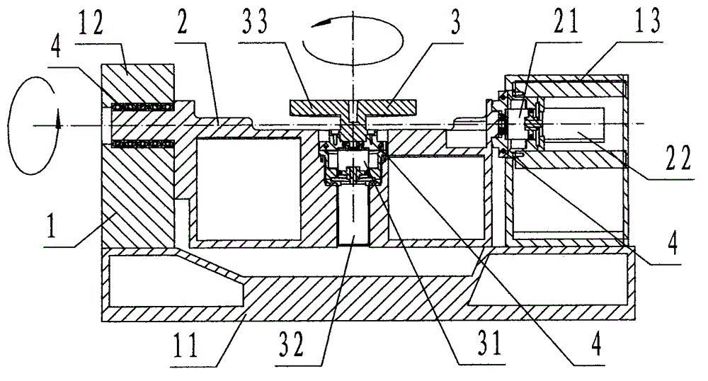
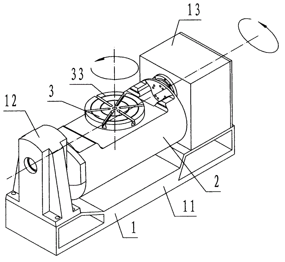
[0017] refer to figure 1 , figure 2 , a numerically controlled four-axis device of the present invention, comprising a base 1, a horizontal rotating shaft 2, and a longitudinal rotating shaft 3, wherein: the base 1 is a concave steel member, and the bottom of the base 1 is a rectangular block The base 11, the left end of the base 11 is fixed with a vertically upwardly protruding support called a bearing frame 12, and the right end of the base 11 is fixed with a vertically upwardly protruding rectangular hollow closed box-shaped support called a support box 13, The upper center of the bearing frame 12 is provided with a circular through hole that runs through the left and right horizontal directions and is called the left bearing hole. The circular through hole is called the right bearing hole, the axes of the left bearing hole and the right bearing hole are correspondingly coincident, and the bearing 4 is arranged in the left bearing hole and the right bearing hole;

[0018...


PUM


Abstract

The invention discloses a numerical control four-shaft device which comprises a base (1), a transverse rotating shaft (2) and a longitudinal rotating shaft (3). The numerical control four-shaft device disclosed by the invention adopts a device which is composed of the base, the transverse rotating shaft and the longitudinal rotating shaft, wherein the transverse rotating shaft is horizontally arranged on the base and is driven by a controlled H servo motor through an H speed reducer, the transverse rotating shaft does a rotating motion around the transverse shaft which is parallel with a working platform; the longitudinal rotating shaft is composed of a Z speed reducer, a Z servo motor and a revolving working platform; the longitudinal rotating shaft is perpendicularly arranged on the center of the transverse rotating shaft; and the revolving working platform is positioned above the transverse rotating shaft and is driven by a controlled Z servo motor through a Z speed reducer, and does the rotating motion around a longitudinal shaft which is orthogonally with the transverse shaft. By adopting the technical scheme that a numerical control system of the common numerical control engraving milling machine tool is utilized to control the H servo motor and the Z servo motor to drive the workpiece to rotate in match with the cutting of a cutting too, the common numerical control engraving milling machine tool is capable of processing a four-shaft processing piece, and the purposes that the cost is reduced and the efficiency is improved are achieved.

Description

technical field [0001] The invention relates to a numerically controlled rotating shaft clamping device, specifically refers to a device for clamping a workpiece on a workbench of an ordinary numerically controlled engraving and milling machine tool, which is controlled to perform numerically controlled four-axis rotational movement around a transverse axis and a longitudinal axis, and cooperates with an ordinary numerically controlled engraving and milling machine tool A CNC four-axis device for homing cutting with a rotating cutting tool moving along the XYZ three axes. Background technique [0002] The rotary cutting tools of ordinary CNC engraving and milling machine tools can only perform cutting motions along the XYZ three-axis, that is, three-axis motion processing; for workpieces that need to cooperate with the cutting tools to revolve around the transverse axis parallel to the worktable and simultaneously around the longitudinal direction perpendicular to the transve...

Claims


Application Information

Patent Timeline
Patent Type & Authority Patents(China)
IPC IPC(8): B23C1/14
Inventor 俞湘谢辉储善谦王永峰徐建国沈良永
Owner 宁波市凯博数控机械有限公司
Learn More