
A vertical CNC drilling and milling machine tool

A drilling and milling machine tool and vertical technology, which is applied to metal processing machinery parts, other manufacturing equipment/tools, large fixed members, etc., can solve the problems of high labor cost, low drilling, tapping and milling processing efficiency and high cost of CNC machining centers. Achieving the effect of low cost, improved efficiency and high efficiency

Active Publication Date: 2016-04-06
宁波市凯博数控机械有限公司
View PDF6 Cites 0 Cited by
  • Summary
  • Abstract
  • Description
  • Claims
  • Application Information

AI Technical Summary

Problems solved by technology

[0002] During equipment manufacturing and processing, such as injection molds, it is necessary to drill, tap, and mill a large number of through holes, blind holes, threaded holes, stepped counterbores, and grooves, tenons, tenons, and slide rails of various shapes on the workpiece. , chute and other hole groove tenon rail structures, the existing technology uses CNC machining center to perform drilling, tapping and milling of hole groove tenon rail structure while processing workpiece surface structure, because CNC machining center is a kind of general and expensive cutting processing equipment , the man-hour cost of CNC machining center is high and the efficiency of drilling, tapping and milling is low. Therefore, the existing technology has the problems and deficiencies of high cost and low efficiency.

Method used


Image

  • A vertical CNC drilling and milling machine tool
  • A vertical CNC drilling and milling machine tool

Examples


Embodiment Construction

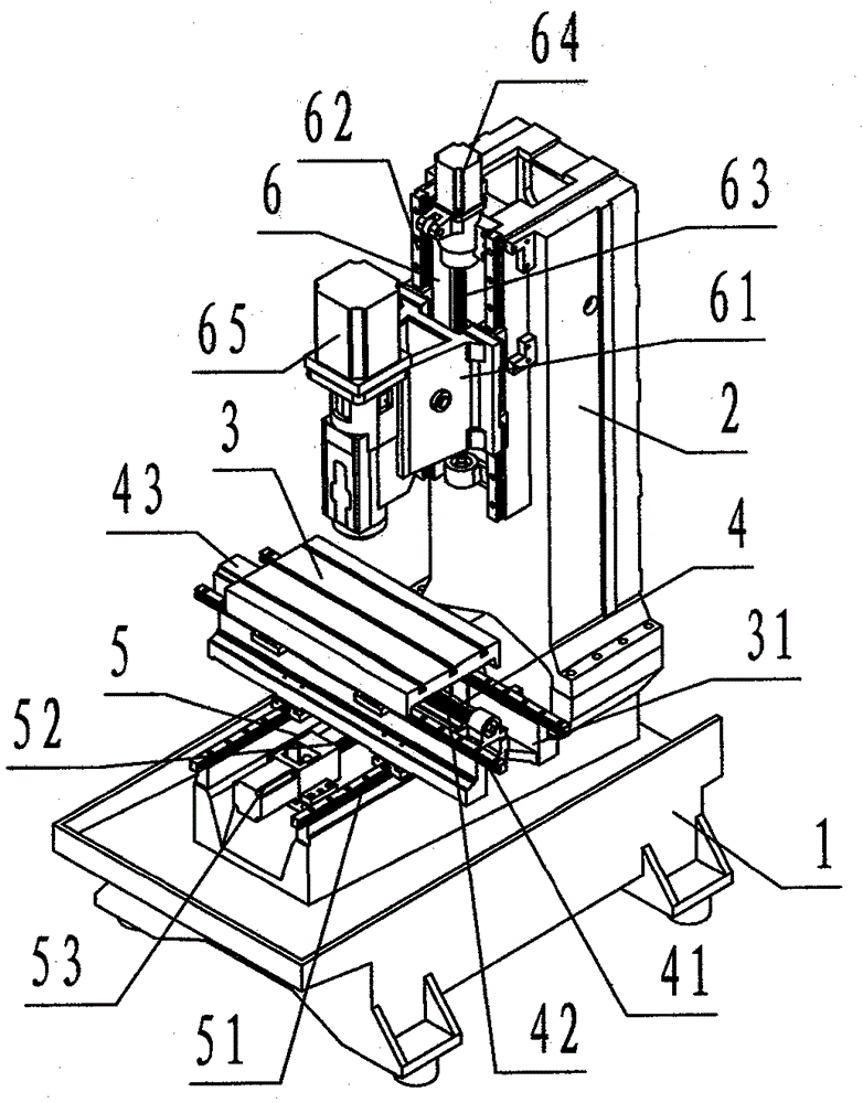
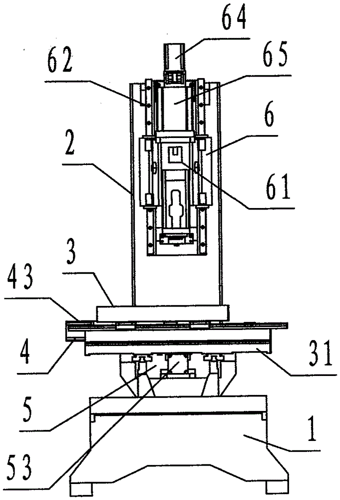
[0026] refer to figure 1 , figure 2 , a vertical CNC drilling and milling machine tool of the present invention, comprising a bed 1, a column 2, a workbench 3, an orthogonal carriage 31, an X slide pair 4, a Y slide pair 5, and a Z slide pair 6, wherein : the bed 1 is a rectangular platform-shaped hollow cast iron member, the bottom four corners of the bed 1 are provided with bed feet; , along the two sides of the center line of the long side, there are two groove-shaped bosses protruding upwards and in the front and rear direction symmetrically, which are called Y-axis connecting seats, and the hollow inner wall of the bed 1 is provided with criss-cross reinforcement ribs;

[0027] The column 2 is a rectangular columnar hollow cast iron component, and the upper middle part of the front of the column 2 is provided with two groove-shaped bosses protruding forward, up and down and parallel to each other, which are called Z-axis connecting seats;

[0028] The workbench 3 is a ...


PUM


Abstract

The invention discloses a vertical type numerical-control drilling and milling machine tool which comprises a lathe bed (1), a stand column (2), a work table (3), an orthogonal carriage (01), an X slide seat pair (4), a Y slide seat pair (5) and a Z slide seat pair (6). With the adoption of the machine tool consisting of the lathe bed, the stand column, the work table, the orthogonal carriage, the X slide seat pair, the Y slide seat pair and the Z slide seat pair, during working, the X slide seat pair and the Y slide seat pair pass the orthogonal carriage and drag the work table carrying workpieces to perform target-seeking movement of a plane coordinate track; the Z slide seat pair carries a spindle motor and a cutting tool to perform vertical target-seeking movement perpendicular to coordinates, and the technical scheme of drilling, tapping and milling is performed; and accordingly, the defects that in prior art, the cost is high and the efficiency is low are overcome, and the machining of drilling, tapping and milling hole, groove, mortise and rail structures of workpieces achieves the purposes of cost reduction and efficiency improvement.

Description

technical field [0001] The invention relates to a numerically controlled cutting machine tool, in particular to a vertical numerically controlled drilling and milling machine tool specially used for drilling, tapping and milling on workpieces. Background technique [0002] During equipment manufacturing and processing, such as injection molds, it is necessary to drill, tap, and mill a large number of through holes, blind holes, threaded holes, stepped counterbores, and grooves, tenons, tenons, and slide rails of various shapes on the workpiece. , chute and other hole groove tenon rail structures, the existing technology uses CNC machining center to perform drilling, tapping and milling of hole groove tenon rail structure while processing workpiece surface structure, because CNC machining center is a kind of general and expensive cutting processing equipment , the man-hour cost of the CNC machining center is high and the efficiency of drilling, tapping and milling is low. The...

Claims


Application Information

Patent Timeline
Patent Type & Authority Patents(China)
IPC IPC(8): B23P23/00B23Q5/40B23Q5/36B23Q1/01
Inventor 李恒国沈良永俞湘储善谦徐建国
Owner 宁波市凯博数控机械有限公司
Learn More