
A self-locking bottle stopper that can release steam gas pressure

A gas pressure and self-locking technology, which is applied in sealing plugs, liquid handling, bottle filling, etc., can solve problems such as lack of heat preservation, bottle liner bursting, etc.

Inactive Publication Date: 2015-09-09
石柱县特色产业生产力促进中心
View PDF6 Cites 0 Cited by
  • Summary
  • Abstract
  • Description
  • Claims
  • Application Information

AI Technical Summary

Problems solved by technology

[0002] As known, thermos bottle is used as a kind of water temperature protection container in many families or office places. When the hot water filled in the bottle liner of the thermos bottle is poured out, a certain space is formed in the bottle liner. The steam expanding in time and space will cause the wooden bottle cork to jump; at this time, the pressure in the bottle liner is greater than atmospheric pressure, so the cork cannot resist the pressure of the hot air in the bottle, causing the cork to jump up and the hot water in the bottle liner to cool down quickly The bottle stopper of the commercially available thermos bottle is a cork material, which is conical with a large upper part and a smaller lower part. The bottle mouth of the thermos bottle liner with poor workmanship is a non-circular structure, and it will not be able to keep warm when it is subjected to the hot air pressure in the bottle. When using a cork material cork, it needs to be pressed down hard to deform the cork. Form a structure that matches the bottle mouth. At this time, once the thickness of the bottle liner is uneven, "sometimes there will be cracks", which will cause the bottle liner to burst

Method used


Image

  • A self-locking bottle stopper that can release steam gas pressure
  • A self-locking bottle stopper that can release steam gas pressure
  • A self-locking bottle stopper that can release steam gas pressure

Examples


Embodiment Construction

[0016] The present invention can be explained in more detail by the following examples, and the purpose of disclosing the present invention is intended to protect all changes and improvements within the scope of the present invention;

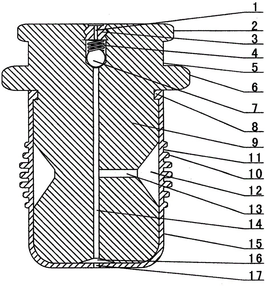
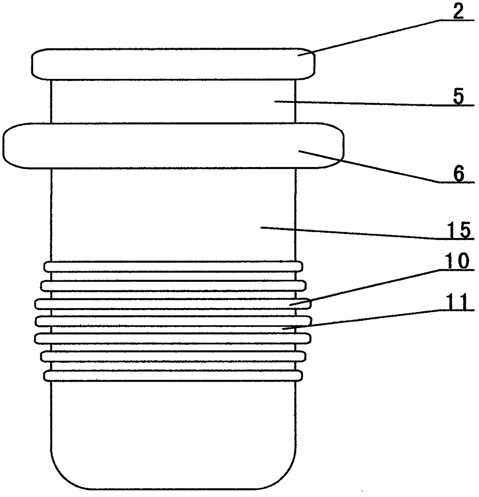
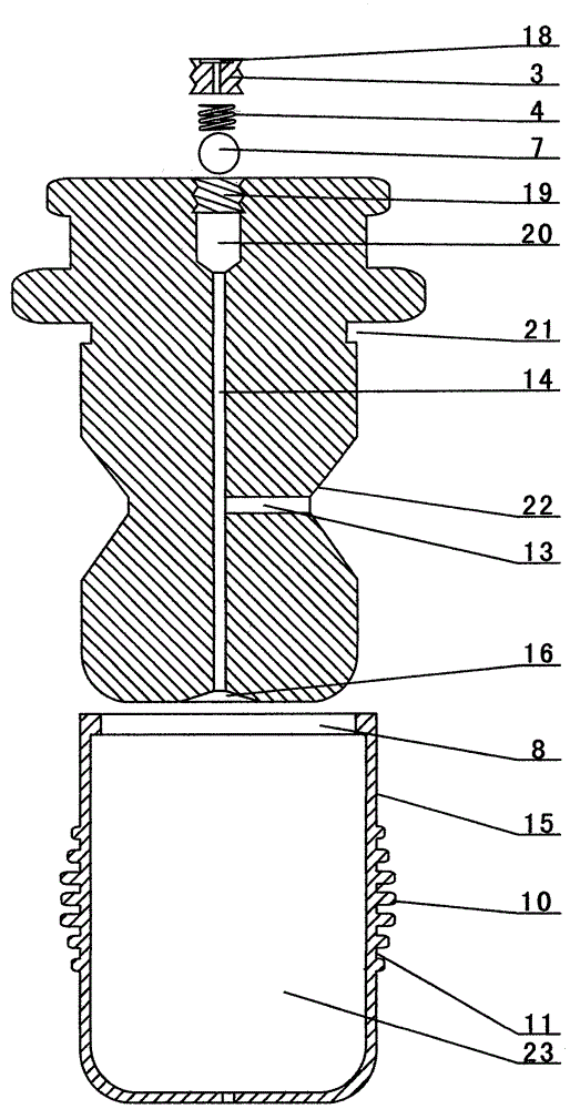
[0017] exist figure 1 , 2 3. The self-locking bottle stopper capable of releasing steam gas pressure, comprising a rubber cylinder 15, an inner cylinder 9, a sphere 7, a spring 4 and an external threaded cylinder 3, and an inner ring 8 is provided on the inner surface of the upper opening of the rubber cylinder 15, The middle part of the outer edge surface of the rubber cylinder 15 is provided with a plurality of surrounding ring-shaped raised strips 10, and the middle part of the lower end of the rubber cylinder 15 is provided with a hole 17; A cylindrical handle 5 is provided, an annular protrusion 2 is provided on the outer edge surface of the upper end of the cylindrical handle 5, and an annular groove 21 is provided near the retaining rin...


PUM


Abstract

The invention provides a self-locking bottle plug capable of releasing steam air pressure and relates to a bottle plug for a thermos bottle. An inner ring 8 of a rubber cylinder 15 is sleeved on an annular groove 21 of the inner column body 9, and a cavity 23 of the rubber cylinder 15 wraps the inner column body 9, a V-shaped annular concave 22 of the inner column body 9 corresponds to an annular protruding strip 10 of the rubber cylinder 15, an air chamber 12 is formed between the V-shaped annular concave 22 of the inner column body 9 and a rubber cylinder 15, a hole 17 of the rubber cylinder 15 corresponds to the lower end of an air drain 14 of the inner column body 9. The annular protruding strip arranged in the self-locking bottle plug capable of releasing steam air pressure can form a close connection with a bottle container port, so that the self-locking bottle plug capable of releasing steam air pressure can be ensured not to separate from the thermos bottle port due to the high pressure in the bottle container. The self-locking bottle plug capable of releasing steam air pressure further has a function of automatically releasing pressure when pressure in a bottle container is too high, consequently, the bottle container can be ensured not to explode.

Description

【Technical field】 [0001] The invention relates to a cork for a thermos bottle, in particular to a self-locking cork capable of releasing steam gas pressure. 【Background technique】 [0002] As known, thermos bottle is used as a kind of water temperature protection container in many families or office places. When the hot water filled in the bottle liner of the thermos bottle is poured out, a certain space is formed in the bottle liner. The steam expanding in time and space will cause the wooden bottle cork to jump; at this time, the pressure in the bottle liner is greater than atmospheric pressure, so the cork cannot resist the pressure of the hot air in the bottle, causing the cork to jump up and the hot water in the bottle liner to cool down quickly The bottle stopper of the commercially available thermos bottle is a cork material, which is conical with a large upper part and a smaller lower part. The bottle mouth of the thermos bottle liner with poor workmanship is a non-...

Claims


Application Information

Patent Timeline
Patent Type & Authority Patents(China)
IPC IPC(8): B65D51/16B65D39/00A47J41/00
Inventor 韩雨吟
Owner 石柱县特色产业生产力促进中心
Learn More