
Barrel tilting device

A pouring device, supporting arm technology, applied in packaging, emptying containers, bottle filling, etc., can solve the problem of wasting time and human resources

Inactive Publication Date: 2013-05-08
DALIAN LONSIN NEW MATERIALS
View PDF0 Cites 15 Cited by
  • Summary
  • Abstract
  • Description
  • Claims
  • Application Information

AI Technical Summary

Problems solved by technology

[0002] Now the general barrels are all done by manpower to dump action, which can only be applied to small barrels, large barrels need to transfer the internal liquid to the small barrels before they can be poured, which wastes time and human resources, and then requires Development of a pouring device capable of pouring large buckets

Method used


Image

  • Barrel tilting device
  • Barrel tilting device

Examples


Embodiment Construction

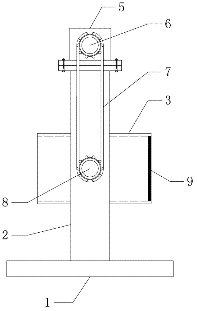
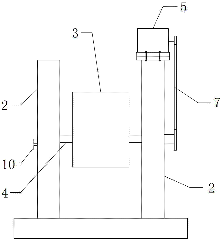
[0010] Such as figure 1 and figure 2 The bucket dumping device shown includes: a base 1, a support arm 2, a dump bucket 3, a rotating shaft 4 and a drive motor 5; the base 1 is fixed on the ground; the support arm 2 is fixed on the upper end surface of the base 1; the dump bucket 3 Connected with the support arm 2 through the rotating shaft 4; the rotating sprocket 8 is fixed at the 3 ends of the non-fixed dumping bucket of the rotating shaft 5; the driving motor 5 is fixed on the upper end of the supporting arm 2 through bolts; the output shaft end of the driving motor 5 is fixed with a driving sprocket 6 The driving sprocket 6 and the rotating sprocket 8 are connected by a chain 7; the electromagnet layer 9 is fixed at the bottom of the dumping bucket 3, and the support arm 2 is provided with a switch button 10 for controlling the electromagnet layer 9 to be energized;

[0011] The user of the present invention who has adopted the above technical solution first places the ...


PUM


Abstract

The invention discloses a barrel tilting device. The barrel tilting device comprises a base, a supporting arm, a tilting barrel, a rotating shaft and a driving motor, wherein the base is fixed on the ground; the tilting barrel is connected with the supporting arm by the rotating shaft; a rotating chain wheel is fixed at the end, which is not fixed with the tilting barrel, of the rotating shaft; a driving chain wheel is fixed at the output shaft end of the driving motor and connected with the rotating chain wheel by a chain; an electromagnet layer is fixed at the bottom of the tilting barrel; and a switch button for controlling the electromagnet layer to be powered up is arranged on the supporting arm. By adopting the technical scheme, a user puts the barrel required to be tilted into the tilting barrel by a hoisting device at first, starts the electromagnet layer at the bottom of the tilting barrel to ensure that the barrel is firmly attracted into the tilting barrel, and starts the driving motor; by using the driving motor, the torque is transmitted to the tilting barrel through the matching of the driving chain wheel, the chain and the rotating chain wheel; and because the tilting barrel is connected with the supporting arm by the rotating shaft, the driving motor can completely control an inclination angle of the tilting barrel.

Description

technical field [0001] The invention relates to a dumping device, in particular to a bucket dumping device. Background technique [0002] Now the general barrels are all done by manpower to dump action, which can only be applied to small barrels, large barrels need to transfer the internal liquid to the small barrels before they can be poured, which wastes time and human resources, and then requires Develop a pouring device capable of pouring large buckets. Contents of the invention [0003] The technical problem to be solved by the present invention is to provide a bucket dumping device. [0004] In order to achieve the above purpose, it is realized through the following technical solutions: [0005] A barrel dumping device, comprising: a base, a support arm, a dumping bucket, a rotating shaft and a drive motor; the base is fixed on the ground; the supporting arm is fixed on the upper end surface of the base; the dumping bucket is connected to the supporting arm through...

Claims


Application Information

Patent Timeline
IPC IPC(8): B65G65/23
Inventor 刘新涛姜维喜陈剑英卞福香穆道旭
Owner DALIAN LONSIN NEW MATERIALS
Features
  • Generate Ideas
  • Intellectual Property
  • Life Sciences
  • Materials
  • Tech Scout
  • Unparalleled Data Quality
  • Higher Quality Content
  • 60% Fewer Hallucinations
Learn More