Supercharge Your Innovation With Domain-Expert AI Agents!

rotary compressor

A rotary compressor and rotary compression technology, applied in the field of rotary compressors, can solve the problems of complicated refrigerant paths, increased cost, increased thickness, etc., so as to suppress the increase in production cost and component cost, suppress the increase in the number of components, The effect of improving workability

Inactive Publication Date: 2015-08-12
SANYO ELECTRIC CO LTD
View PDF11 Cites 0 Cited by
  • Summary
  • Abstract
  • Description
  • Claims
  • Application Information

AI Technical Summary

Problems solved by technology

[0008] However, in the prior art in which an oil separation mechanism is provided between the rotary compression mechanism part and the airtight container, at least the radial dimension of the airtight container has to be increased correspondingly.
In addition, since the number of parts constituting the compressor is also significantly increased, there is also a problem of cost increase
[0009] Therefore, instead of providing an oil separation mechanism using centrifugal force between the rotary compression mechanism part and the airtight container, it has been proposed to provide an oil separator on the cover that closes the recess of the support member constituting the discharge muffler chamber of the second rotary compression unit. However, the thickness of the cover that can only ensure a certain strength increases, so that the expansion of the axial dimension of the airtight container becomes a problem, and there is also a horizontal rotary compressor that is not easy but can be compressed in a vertical rotary compressor. The problem that the path of the refrigerant flowing from the discharge muffler chamber to the oil separation mechanism in the cover becomes complicated (for example, refer to the above-mentioned Patent Document 2)

Method used


Image

  • rotary compressor
  • rotary compressor
  • rotary compressor

Examples


Embodiment 2

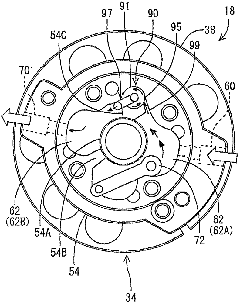
[0090] the following, Figure 5 with Image 6 A plan view (except for the upper cover 66 and the gasket 65) of the rotary compression mechanism portion 18 of the rotary compressor 10 of another embodiment of the present invention and its enlarged view are shown. At this time, the oil separation mechanism 90 is provided at two locations (90A, 90B) on the partition wall 54C of the upper support member 54, an introduction passage 99 communicating with the refrigerant introduction portion 95 of the first oil separation mechanism 90A, and a discharge valve 72 The discharge muffler chamber 62 (62A) on the side communicates with the refrigerant outlet 97 of the oil separation mechanism 90A and the introduction passage 99 of the second oil separation mechanism 90B. The refrigerant outlet 97 of the second oil separation mechanism 90B communicates with the discharge passage The discharge muffler chamber 62 (62B) on the 70 side communicates.

[0091] That is, in this embodiment, two oil sep...

Embodiment 3

[0094] the following, Figure 7 with Picture 8 A plan view (except for the upper cover 66 and the gasket 65) and an enlarged view of the rotary compression mechanism portion 18 of the rotary compressor 10 according to another embodiment of the present invention. At this time, the oil separation mechanism 90 is provided on the partition wall 54B and the partition wall 54C of the upper support member 54 respectively, and there are two (90A, 90B) in total, which are the same as the first and second oil separation mechanisms 90A, 90B. The introduction passage 99 communicating with the agent introduction portion 95 communicates with the discharge muffler chamber 62 (62A) on the discharge valve 72 side, and the refrigerant outlet portions 97 of the first and second oil separation mechanisms 90A and 90B are respectively connected to the discharge passage 70 side. The muffler chamber 62 (62B) communicates.

[0095] That is, in this embodiment, two oil separation mechanisms 90 (90A, 90B...


PUM


Abstract

The invention relates to a rotary compressor, which can avoid dimension increase of the closed container when reducing the amount of oil discharged out of the closed container through centrifugal separation, and inhibit increase of cost. The rotary compressor (10) is composed of an electric unit (14) contained in a closed container (12), and a rotary compression mechanism (18) driven by a rotating shaft (16) of the electric unit (14), wherein the rotary compression mechanism (18) is provided with an upper cylinder (38), an upper support component (54) and an oil separation device (90) formed on the upper support component (54); the cylinder (38) is provided with a compression chamber for compressing a refrigerant internally; the upper support component (54) seals the compression chamber and is provided with a discharging and silencing chamber (62); the compressed refrigerant in the cylinder (38) is discharged to the discharging and silencing chamber (62); and the oil separation device (90) is used for carrying out centrifugal separation on oil in the refrigerant discharged into the discharging and silencing chamber (62).

Description

Technical field [0001] The present invention relates to a rotary compressor constructed by accommodating an electric unit and a rotary compression mechanism driven by the electric unit in a closed container. Background technique [0002] At present, such compressors have, for example, an internal intermediate pressure type multi-stage (two-stage) compression type rotary compressor having a first and a second rotary compression unit, which is configured to house an electric unit and a rotary compression driven by the electric unit in a closed container. Institutional Department. The refrigerant gas is sucked from the suction port of the first rotary compression unit to the low pressure chamber side of the cylinder, and compressed by the action of the rotor and vanes to become intermediate pressure, and then from the high pressure side of the cylinder through the discharge port and discharged from the muffler chamber to the airtight container Exhaust within. The intermediate pres...

Claims


Application Information

Patent Timeline
Patent Type & Authority Patents(China)
IPC IPC(8): F04C23/00F04C29/02
Inventor 佐藤孝桥本刚志阿巴斯塔利今井悟益川贵之
Owner SANYO ELECTRIC CO LTD
Features
  • R&D
  • Intellectual Property
  • Life Sciences
  • Materials
  • Tech Scout
  • Unparalleled Data Quality
  • Higher Quality Content
  • 60% Fewer Hallucinations
Learn More