Cooling bearings, motors and other rotating heat generating components

A technology for heat-generating components and bearings, which is applied in the direction of bearing components, bearing cooling, electric components, etc., and can solve problems such as the reduction of thermal conductivity and heat transfer

Active Publication Date: 2009-05-27
SMJA HLDG
View PDF1 Cites 12 Cited by
  • Summary
  • Abstract
  • Description
  • Claims
  • Application Information

AI Technical Summary

Problems solved by technology

At pressures where the mean free path of the gas molecules is greater than the distance between surfaces, the gas molecules continue to

Method used


Image

  • Cooling bearings, motors and other rotating heat generating components
  • Cooling bearings, motors and other rotating heat generating components
  • Cooling bearings, motors and other rotating heat generating components

Examples


Embodiment Construction

[0040] There are many possible implementations of the present invention, and there are too many to explain here. Some preferred embodiments are described below. These are descriptions of the embodiments of the present invention, rather than descriptions of the present invention. The present invention is not limited to the details described here, but is described by the general terms of the claims.

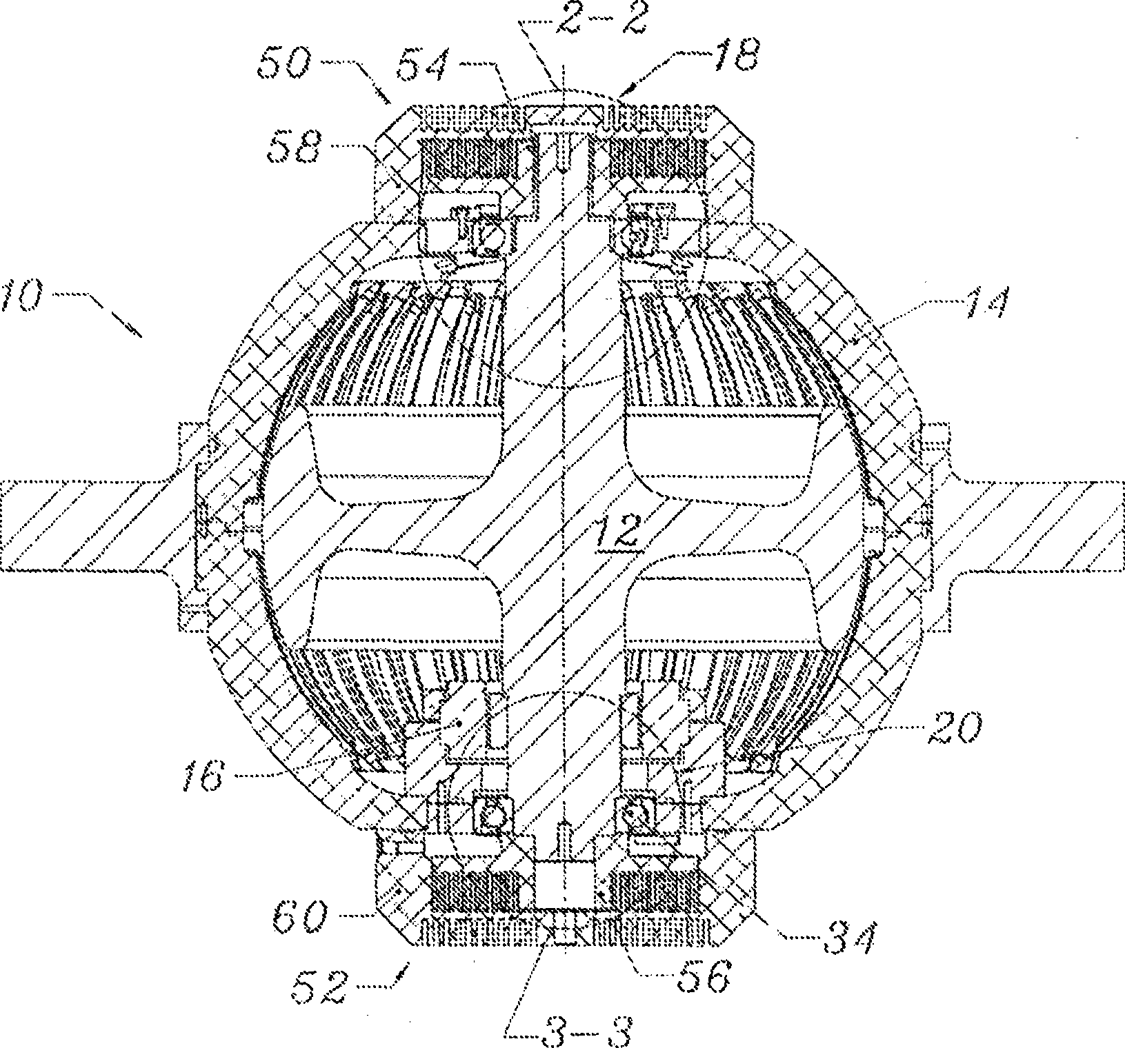
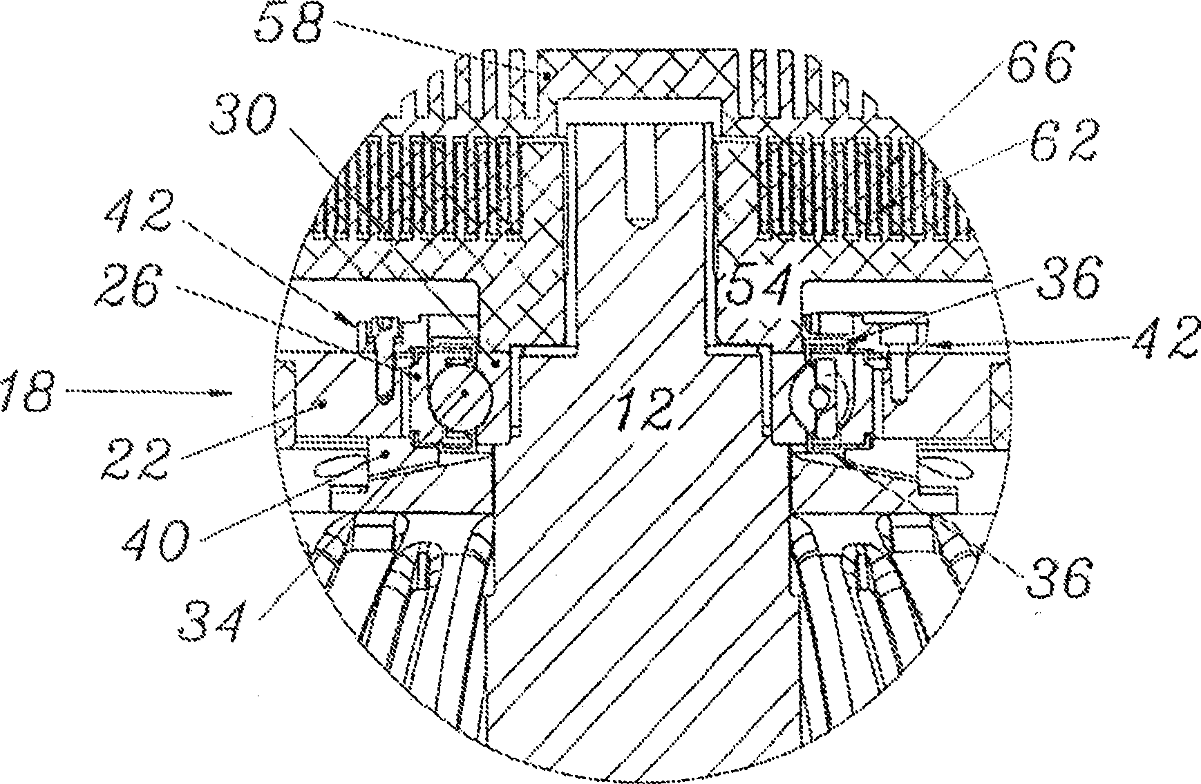
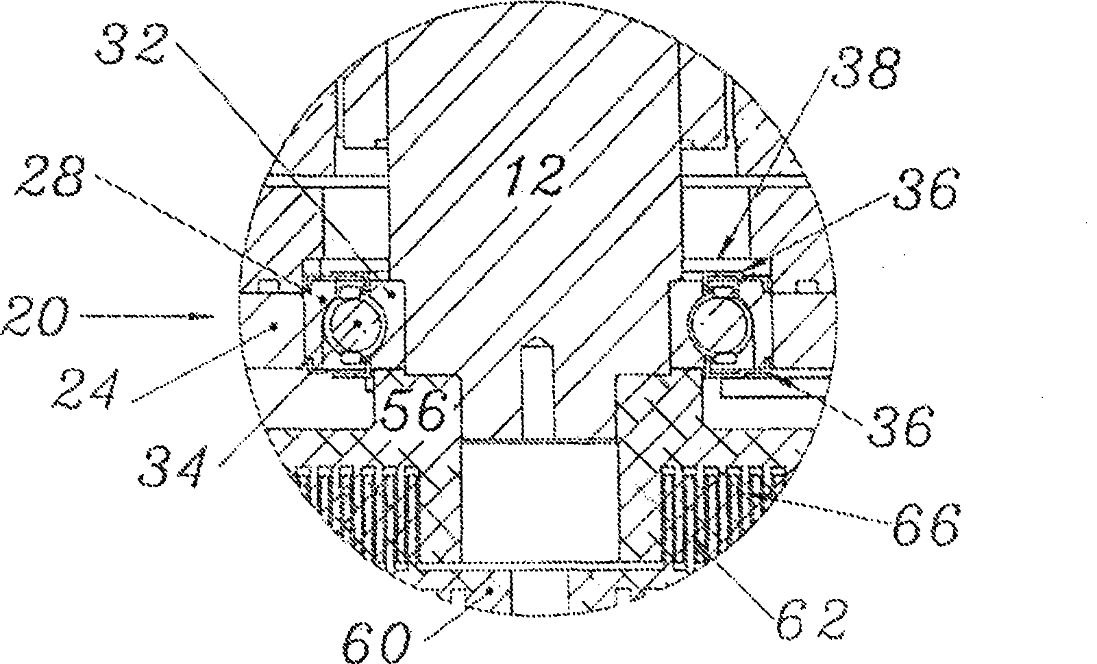
[0041] figure 1 A gyroscope roll stabilizer 10 representing a ship (of the type described in U.S. Patent No. 6,973,847, which is incorporated herein by reference). The steel flywheel 12 rotates in an aluminum housing 14, which is evacuated to a pressure lower than the surrounding pressure and may include a gas with a lower density than the surroundings (such as helium or hydrogen) in order to reduce friction on the rotating flywheel . A motor (a frameless and brushless DC motor) integrally made inside the housing drives a flywheel supported by the upper bearing assembly 18 and the lo...


PUM


Abstract

Cooling apparatus for transferring heat from and cooling one or more heat generating components that support or drive a flywheel or other spinning members. The apparatus may include a first heat transfer element connected to and spinning with the spinning member, a second heat transfer element stationary with respect to the spinning member, wherein the first and second heat transfer elements moverelative to one another, and wherein the first and second heat transfer elements are shaped and positioned in close proximity to one another so that substantial heat is transferred from the first heat transfer element to the second heat transfer element.

Description

Technical field [0001] The present invention relates to a method and device for cooling bearings, motors, and other heat-generating components that support and drive rotating machinery (such as a flywheel sealed in a partial vacuum). Background technique [0002] The control moment gyroscope ("CMG") used to reduce ship sway is operated by a heavy flywheel that works at a high rotation speed. The spinning flywheel is supported by bearings subjected to large axial and radial loads. As a result, these bearings generate a lot of heat generated by friction, which must be dissipated in order to avoid the formation of dangerous heat. If the flywheel is supported in a conventional external environment, the heat can be dissipated by air convection, and the fan can be used to blow air through the inner and outer raceways of the bearing and adjacent metal parts to help dissipate heat. However, if the flywheel is enclosed in a partial vacuum, as described in our patent-US Patent No. 6,973,84...

Claims


Application Information

Patent Timeline
IPC IPC(8): H02K9/00
CPCG01C19/00F16C37/007B63B39/04F16C2370/00F16F15/30Y10T74/12Y10T74/1207Y10T74/1296
Inventor 约翰·D·亚当斯谢泼德·W·麦肯尼
Owner SMJA HLDG
Why Eureka
Try Eureka