Main-shaft lubrication device

a lubricant oil supply and main shaft technology, applied in the direction of lubrication elements, bearing components, shafts and bearings, etc., can solve the problems of destabilizing the oil film, difficult to check the amount of lubricant oil which actually exists around the rolling surface of the bearing and the rolling member, and relates, so as to increase the amount of collected lubricant oil, increase the amount of lubricant oil, and optimize the amount of supplied lubricant oil

Inactive Publication Date: 2008-05-15
OKUMA CORP
View PDF14 Cites 14 Cited by
  • Summary
  • Abstract
  • Description
  • Claims
  • Application Information

AI Technical Summary

Benefits of technology

[0011]With the main-shaft lubrication device according to the present invention, when the amount of lubricant oil collected from the main-shaft bearing is large, it is possible to determine that the amount of supplied lubricant oil is large and to reduce the amount of oil, and when the amount of lubricant oil collected from the main-shaft bearing is small, it is possible to increase the amount of lubricant oil to be supplied, which enables maintaining an optimum lubrication state.
[0012]Further, the bearing may include an inner ring and an outer ring which sandwich rolling members, and the outer ring may be provided with a lubricant oil ejection hole extending in a radial direction from its inner peripheral surface to its outer peripheral surface, so that the collection part can collect the lubricant oil through the lubricant oil ejection hole. This enables grasping, more accurately, the amount of lubricant oil relating to the formation of an oil film between the rolling members and the surface on which the rolling members roll. Further, when a lubricant oil supply path is provided near the surface of the bearing on which the rolling members roll, it is possible to supply a minimum amount of lubricant oil necessary for formation of the oil film. For example, in the bearing constituted by the outer ring, the inner ring, the rolling members and a holding member, a lubricant oil supply through hole and a lubricant oil collection through hole can be provided in the surface of the outer ring on which the rolling members roll, at a position through which the rolling member does not pass, for adjusting the amount of lubricant oil.
[0014]Also, the main-shaft lubrication device may include at least one sensor, and information obtained from the sensor can be reflected on the amount of lubricant oil to be supplied from the supply part. This enables taking account of the information obtained from the sensor in determining the amount of lubricant oil to be supplied to the bearing from the amount of collected lubricant oil, thereby enabling provision of an amount of lubricant oil on which the state of the bearing is further reflected. For example, there will be considered a case where a sensor for detecting the rotation speed of the main shaft is mounted to the main shaft. When the rotation speed of the main shaft is high, the lubricant oil is scattered to portions other than the surface of the bearing on which the rolling members roll due to centrifugal force, which increases the amount of collected lubricant oil. Therefore, in this case, by increasing the amount of lubricant oil to be supplied in comparison with a case where the rotation speed of the main shaft is low, it is possible to optimize the amount of supplied lubricant oil.
[0016]According to the present invention, the amount of lubricant oil to be supplied is determined on the basis of the amount of lubricant oil around the bearing which relates to formation of an oil film in the bearing, which enables optimization of the amount of lubricant oil in the bearing. Further, the amount of collected lubricant oil is monitored, which is effective in detecting abnormalities of the lubricant oil supply device, the lubricant oil supply path and the bearing. Further, information obtained from the sensor, such as the temperature and the rotation speed of the main shaft, can be reflected on the amount of lubricant oil to be collected, which enables determination of an optimum amount of lubricant oil for the state of operation of the main shaft.

Problems solved by technology

In this case, it is difficult to adjust the amount of lubricant oil with the grease lubrication method.
With such a conventional device, it is possible to check the amount of lubricant oil supplied to the bearing, but it is difficult to check the amount of lubricant oil which actually exists around the rolling surface of the bearing and the rolling members and relates to lubrication, after the lubricant oil is supplied.
This may result in a superfluity or shortage of lubricant oil, thereby destabilizing the oil film.
This may make it difficult to rotate the main shaft with high accuracy and, in the worst case, may produce abnormal heat, thereby damaging the bearing.
With this conventional device, it is difficult to determine whether the temperature rise is caused by the shortage of lubricant oil or the superfluity of lubricant oil and also whether the temperature rise is caused by an influence of a motor in the case where the main shaft includes the motor near the bearing.

Method used


Image

  • Main-shaft lubrication device
  • Main-shaft lubrication device
  • Main-shaft lubrication device

Examples


Embodiment Construction

[0026]Hereinafter, embodiments of the present invention will be described with reference to the drawings.

[0027]In the following description, “left” and “right” are defined such that the left side in FIG. 1 is referred to as a “left side” and the side opposite therefrom is referred to as a “right side”. Further, the left side denotes a front side, and the right side denotes a rear side.

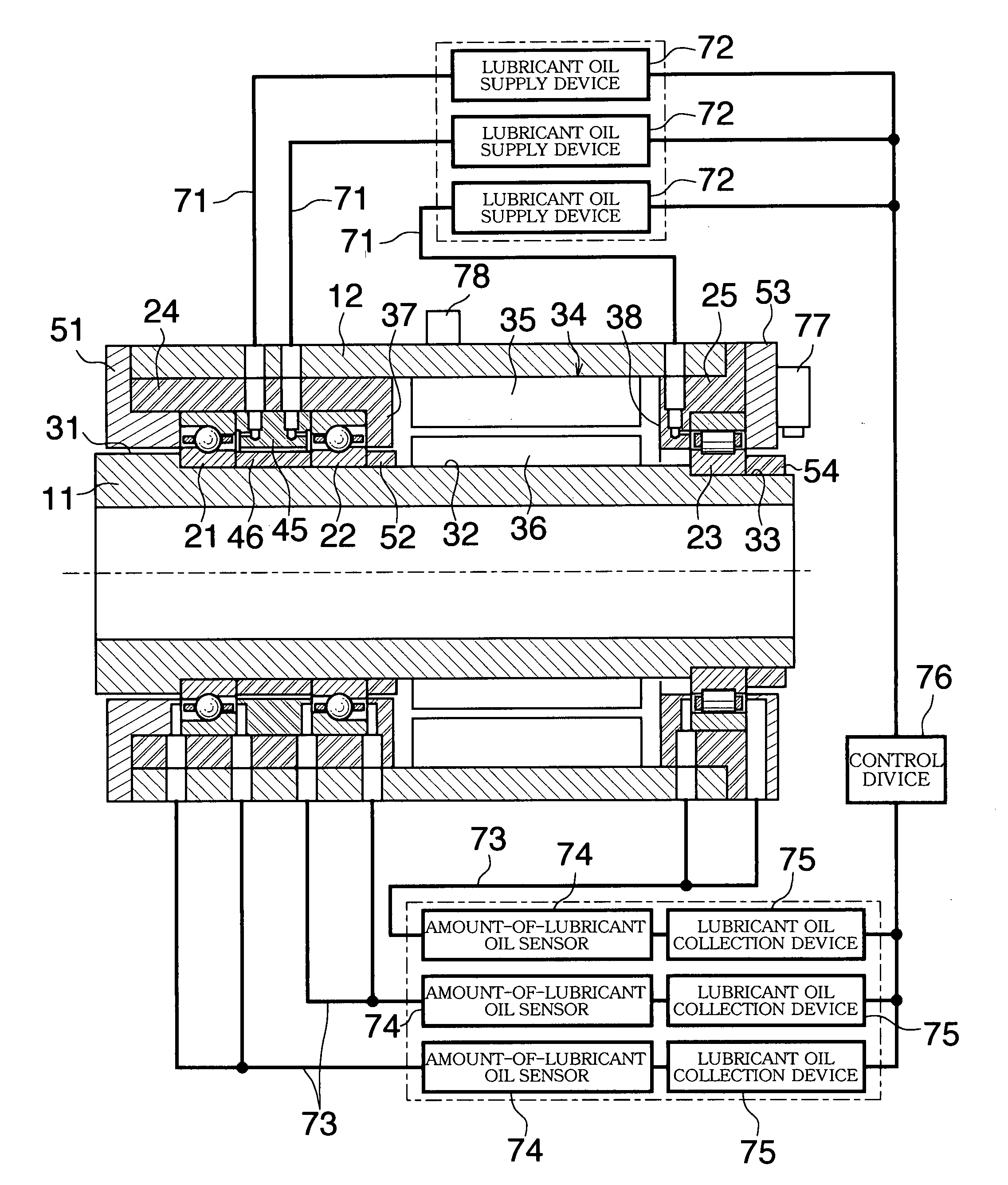
[0028]A main shaft device includes a horizontal hollow-shaft-shaped main shaft 11, a horizontal cylindrical-shaped sleeve 12 surrounding the main shaft 11, a first bearing 21 and a second bearing 22 which are axially spaced apart from each other for supporting the left side of the main shaft 11, a third bearing 23 for supporting the right side of the main shaft 11, a left-side housing 24 secured to the inner surface of the sleeve 12 such that it surrounds the first bearing 21 and the second bearing 22, and a right-side housing 25 secured to the inner surface of the sleeve 12 such that it surrounds the ...


PUM


Abstract

The amount of lubricant oil supplied to a bearing is optimized. A main-shaft lubrication device includes a supply device for variably supplying lubricant oil to bearings which support a main shaft, a collection device for collecting, from the bearings, the lubricant oil supplied from the supply device, a measurement device for measuring the amount of lubricant oil collected by the collection device, and a control device for controlling the amount of lubricant oil to be supplied from the supply device.

Description

BACKGROUND OF THE INVENTION[0001]1. Field of the Invention[0002]The present invention relates to a main-shaft lubricant oil supply device for adjusting the amount of to-be-supplied lubricant oil to an optimum amount, by detecting the amount of collected lubricant oil.[0003]2. Description of the Related Art[0004]For example, a machining tool is rotatably supported at its main shaft by a plurality of rolling bearings. Generally, a bearing is constituted by an inner ring, an outer ring, a plurality of rolling members and a holding device for holding the rolling members at equal intervals, wherein the rolling members are movably incorporated therein. The inner ring is press-fitted to the main shaft and is rotated together with the main shaft, and the outer ring is incorporated in a housing and is secured by being pressed in the axial direction by a pressing lid. Lubricant oil is filled in or supplied to the bearing, and an oil film is formed between the inner ring and outer ring and the...

Claims


Application Information

Patent Timeline
Patent Type & Authority Applications(United States)
IPC IPC(8): F16N29/04
CPCF16C33/6674
Inventor YANOHARA, NAOMITSUNORIHISA, TAKASHIANDO, TOMOHARU
Owner OKUMA CORP
Why Eureka
Try Eureka