Variable displacement gerotor pump

a gerotor pump and variable displacement technology, applied in the field of oil pumps, can solve the problems of narrow tolerance design, excessive oil pressure at higher engine speeds, and hinder the operation of the valve or destroy the valve, so as to reduce the amount of oil pumped

Inactive Publication Date: 2008-01-24
METALDYNE LLC
View PDF35 Cites 15 Cited by
  • Summary
  • Abstract
  • Description
  • Claims
  • Application Information

AI Technical Summary

Benefits of technology

[0008] The present invention provides an oil pump capable of reducing the amount of oil pumped per revolution so as not to pump excess oil at high engine speeds. Specifically, the present invention relates to a variable displacement gerotor pump capable of providing variable amounts of oil per revolution of the engine. In known gerotor pumps, the position of the outer rotor is fixed. As a result, the gerotor rotates to transfer a fixed amount of fluid per revolution.

Problems solved by technology

However, the valve is designed with narrow tolerances and foreign material entering the valve hinders the operation of the valve or destroys the valve.
During a second part of the rotation cycle, the area between the rotors decreases, causing compression.
Otherwise, oil pressure will become excessive at higher engine speeds.

Method used


Image

  • Variable displacement gerotor pump
  • Variable displacement gerotor pump
  • Variable displacement gerotor pump

Examples


Embodiment Construction

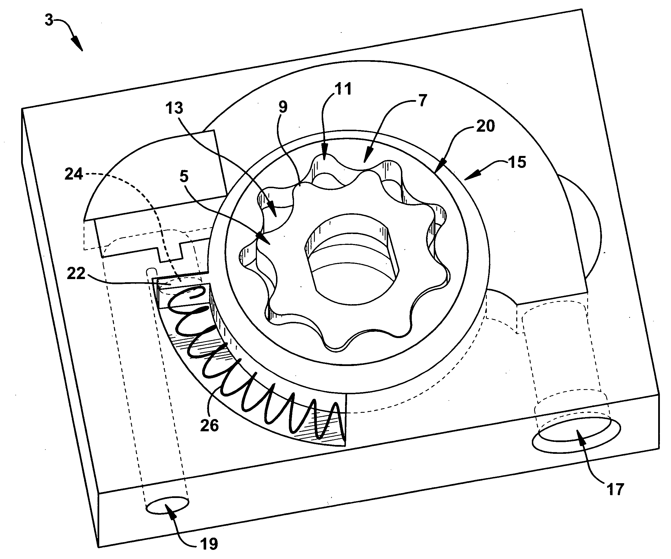
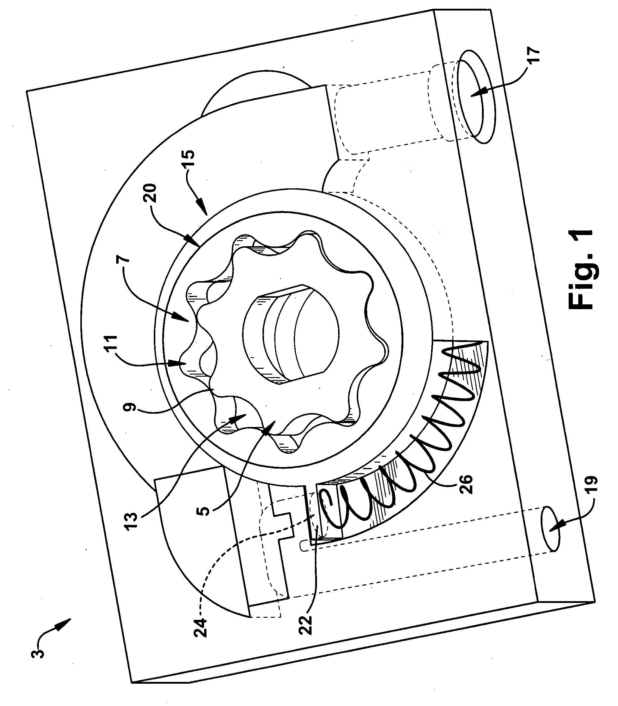
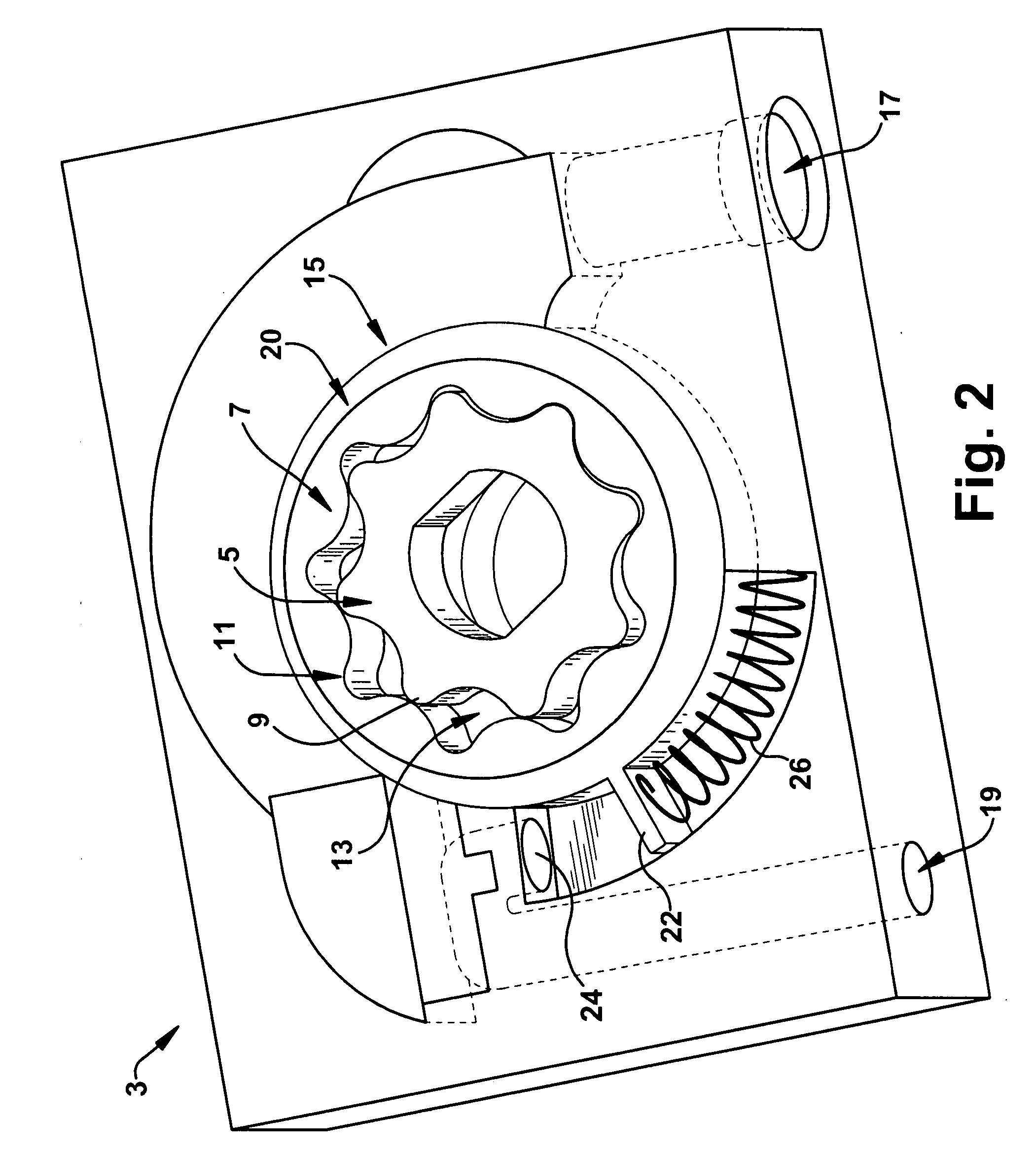
[0021] The present invention is described as being implemented for use in an engine to, for example, pump oil; however, it is clearly contemplated that the present invention may be incorporated into other systems and may be used to pump other fluids as known to one of ordinary skill in the art. The present invention advantageously responds to increasing fluid pressure by reducing output flow. For example, the higher the oil pressure, the lower the rate of pumping of the fluid of the present invention.

[0022] As illustrated in FIGS. 1 and 2, a variable displacement pump 3, such as a gerotor pump, may have an inner rotor 5 (or gerotor) in meshed engagement with an outer rotor 7. The inner rotor 5 may rotate with respect to the outer rotor 7. For example, the inner rotor 5 may rotate in a counterclockwise direction. Of course, the present invention could be implemented such that the gerotor 5 rotates in a counterclockwise direction or other direction as will be appreciated by one of or...


PUM


Abstract

A variable displacement pump having an inner rotor (gerotor) and an outer rotor is disclosed. Advantageously, the pump provides a movable outer rotor capable of changing the amount of fluid transferred from an inlet to an outlet. Optionally, a biasing member is connected to the outer rotor for preventing movement of the outer rotor below a predetermined amount of pressure at the outlet.

Description

CROSS-REFERENCE TO RELATED APPLICATIONS [0001] This application claims priority from U.S. Provisional Patent Application No. 60 / 788,324 entitled “VARIABLE DISPLACEMENT PUMP” filed on Mar. 31, 2006; U.S. Provisional Patent Application No. 60 / 849,659 entitled “VARIABLE DISPLACEMENT GEROTOR PUMP” filed on Oct. 5, 2006; U.S. Provisional Patent Application No. 60 / 849,673 entitled “VARIABLE DISPLACEMENT GEROTOR PUMP” filed on Oct. 5, 2006; U.S. Provisional Patent Application No. 60 / 850,466 entitled “VARIABLE DISPLACEMENT GEROTOR PUMP” filed on Oct. 10, 2006; and U.S. Provisional Patent Application No. 60 / 850,666 entitled “VARIABLE DISPLACEMENT GEROTOR PUMP” filed on Oct. 10, 2006, each of which is hereby incorporated by reference in its entirety.FIELD OF THE INVENTION [0002] The present invention generally relates to an oil pump for a vehicle, and more particularly, to a variable displacement gerotor pump. BACKGROUND OF THE INVENTION [0003] Combustion engine vehicles require lubrication s...

Claims


Application Information

Patent Timeline
Patent Type & Authority Applications(United States)
IPC IPC(8): F04B49/08
CPCF04C14/14F04C2/102
Inventor WHITE, STEPHEN L.TITUS, BARRY C.SPICUZZA, SCOTTHALE, ALLEN W.DE KONING, JAN C.
Owner METALDYNE LLC
Why Eureka
Try Eureka