Lung ventilator and/or anaesthesia machine

A technology for lung ventilation, anesthesia machine, applied in the field of lung ventilator and/or anesthesia machine, which can solve the problems of increasing space requirements and weight

Inactive Publication Date: 2013-05-08
IMT股份公司
View PDF11 Cites 11 Cited by
  • Summary
  • Abstract
  • Description
  • Claims
  • Application Information

AI Technical Summary

Problems solved by technology

[0016] A particular disadvantage is the pressurized container used to store the gas mixture, which considerably increases the space requirements and weight

Method used


Image

  • Lung ventilator and/or anaesthesia machine

Examples


Embodiment Construction

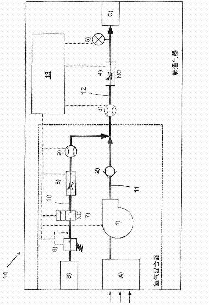
[0047] figure 1 A lung ventilator 14 according to the invention is shown, for example a (mobile) home lung ventilator or a lung ventilator or anesthesia machine for use in an intensive care unit or operating theater. Functionally, the lung ventilator 14 is divided into two areas: the mixer and the vent, where medical gases such as oxygen, nitric oxide, various other anesthetics, gaseous pain relievers, etc. are mixed with air and the resulting The gas mixture is supplied to the patient via the vent as breathing gas at the appropriate pressure and flow rate (dose amount). The lung ventilator 14 thus comprises a gas line 10 and an air line 11 , which lead to a common breathing air line 12 .

[0048] A gas inlet B, for example in the form of a connection point for a high-pressure gas cylinder or a connection for a high-pressure gas network, leads to a gas line 10 into which the medical gas flows. On the inlet side, the gas line 10 has a valve 6, usually a pressure reducing valv...


PUM


Abstract

Lung ventilator (14) and / or anaesthesia machine with a blender for mixing a pressurised medical gas, e.g. oxygen, with air drawn in by a blower (1 ), comprising a gas line (10) for the medical gas, and an air line (1 1 ), which open into a common breathing gas line (12), whereby the opening of the gas line (10) into the common gas line (12) is downstream of the blower (1 ) and in the gas line (10) a regulating valve (8) is provided for variable adjustment of the gas flow and in the common breathing gas line (12) a regulating valve (4) is provided for dosing the breathing gas, and whereby in the breathing gas line (12) a flow sensor (3) is provided for measuring the breathing gas flow and in the gas line (10) a flow sensor (9) is provided for measuring the gas flow.

Description

[0001] This application claims the benefit of prior U.S. Provisional Application No. 61 / 381,056, filed September 8, 2010 and as priority to its non-provisional application; this application also claims the benefit of European Patent Application No. EP10175668, filed September 7, 2010 Right of Priority; European Patent Application No. EP10175668 and US Patent Application No. 61 / 381,056 are hereby expressly incorporated by reference in their entirety for all intents and purposes as if set forth identically herein. technical field [0002] The invention relates to a lung ventilator and / or anesthesia machine with a mixer for mixing pressurized medical gas such as oxygen with air drawn by a blower, comprising an air line and a gas line for the medical gas, air The tubing and the gas line lead to a common breathing gas line. [0003] The present invention relates to a method of operating a lung ventilator and / or anesthesia machine in which breathing gas is provided by mixing a press...

Claims


Application Information

Patent Timeline
Patent Type & Authority Applications(China)
IPC IPC(8): A61M16/01A61M16/12
CPCA61M2016/0027A61M16/01A61M2016/0039A61M2202/0208A61M2016/125A61M16/208A61M2016/204A61M16/12A61M16/0066A61M2016/203A61M16/107A61M16/125A61M16/203A61M16/204
Inventor 哈利·弗里博格雅各布·德谢尔
Owner IMT股份公司
Why Eureka
Try Eureka