Apparatus and method for providing high frequency variable pressure to a patient

a technology of high frequency variable pressure and apparatus, which is applied in the direction of valve details, valve arrangement, operating means/releasing devices of valves, etc., can solve the problems of gas diffusion, patient using the ventilator to face gas diffusion problems, and create a disproportionate gas exchange in the lungs

Inactive Publication Date: 2004-03-23
RIC INVESTMENTS LLC
View PDF16 Cites 155 Cited by
  • Summary
  • Abstract
  • Description
  • Claims
  • Application Information

AI Technical Summary

Problems solved by technology

In either of these situations, it is not uncommon for the patient using the ventilator to face gas diffusion problems, secretion clearance problems, or both.
Gas diffusion problems occur when the breathing gas supplied to the patient is not uniformly distributed through the lungs.
This difference between the extension in the healthy part and the not-as-healthy part of the lung can exacerbate the patient's lung condition, create a disproportionate gas exchange in the lungs, and may eventually damage the entire lung.
Secretion clearance problems occur when there is a build up of secretions in the patient's respiratory system.
In a ventilated patient, however, these secretion clearing movements cannot be performed easily, and, in some cases, cannot be performed at all.
If the secretions are not removed in some other manner, they can accumulate in the patient, which increases the difficulty of properly ventilating the patient.
While these ventilation techniques are believed to be effective in creating pressure oscillations in the primary flow of gas, they are disadvantageous in that they do not allow the pressure delivered to the patient to be a negative pressure during the oscillation cycle.
In addition, it is difficult to control the oscillation magnitude and frequency with a high degree of precision and controllability while at the same time minimizing the complexity of the pressure oscillation generating mechanisms.
Also, the above-described pressure oscillation techniques can only provide a somewhat limited range of magnitudes for the pressure variations in each oscillation cycle.
For ventilation devices that use a flexible diaphragm to create the pressure oscillations, this limited range of magnitude in the pressure variation is due to the fact that a diaphragm displaces a finite amount of gas.
In addition, the gas pulses have a limited affect on the primary gas flow.
Secretion clearance can also be a problem in patients that are not using a ventilator.
For example, a patient with a weakened respiratory system may not be physically able to perform a secretion clearing movement with sufficient strength or force to remove or loosen the secretions.
There are disadvantages associated with the flutter valve secretion clearance device.
For example, proper seating of the ball on the valve seat is only possible if the device is held in its upright position.
Therefore, the device is very position sensitive.
In addition, because the patient's own expiratory force is used to move the ball to the open position, the flutter valve cannot be used by patients with very weak respiratory systems who have very low expiratory flow.
There is a significant disadvantage in the above-described pressure oscillation technique.
Namely, the frequency of oscillation is limited to a relatively low level due to the fact that the device physically moves a portion of the patient circuit in a windshield wiper fashion.
It is simply not possible to provide an oscillation frequency greater than approximately 2 Hz using this system.
In addition, this system does not allow a pressure oscillation waveform to be superimposed on a second pressure waveform.
In addition, the valve at least partially restricts communication of the source of breathing gas with the airway of the patient when in a second position within the patient circuit.

Method used


Image

  • Apparatus and method for providing high frequency variable pressure to a patient
  • Apparatus and method for providing high frequency variable pressure to a patient
  • Apparatus and method for providing high frequency variable pressure to a patient

Examples


Embodiment Construction

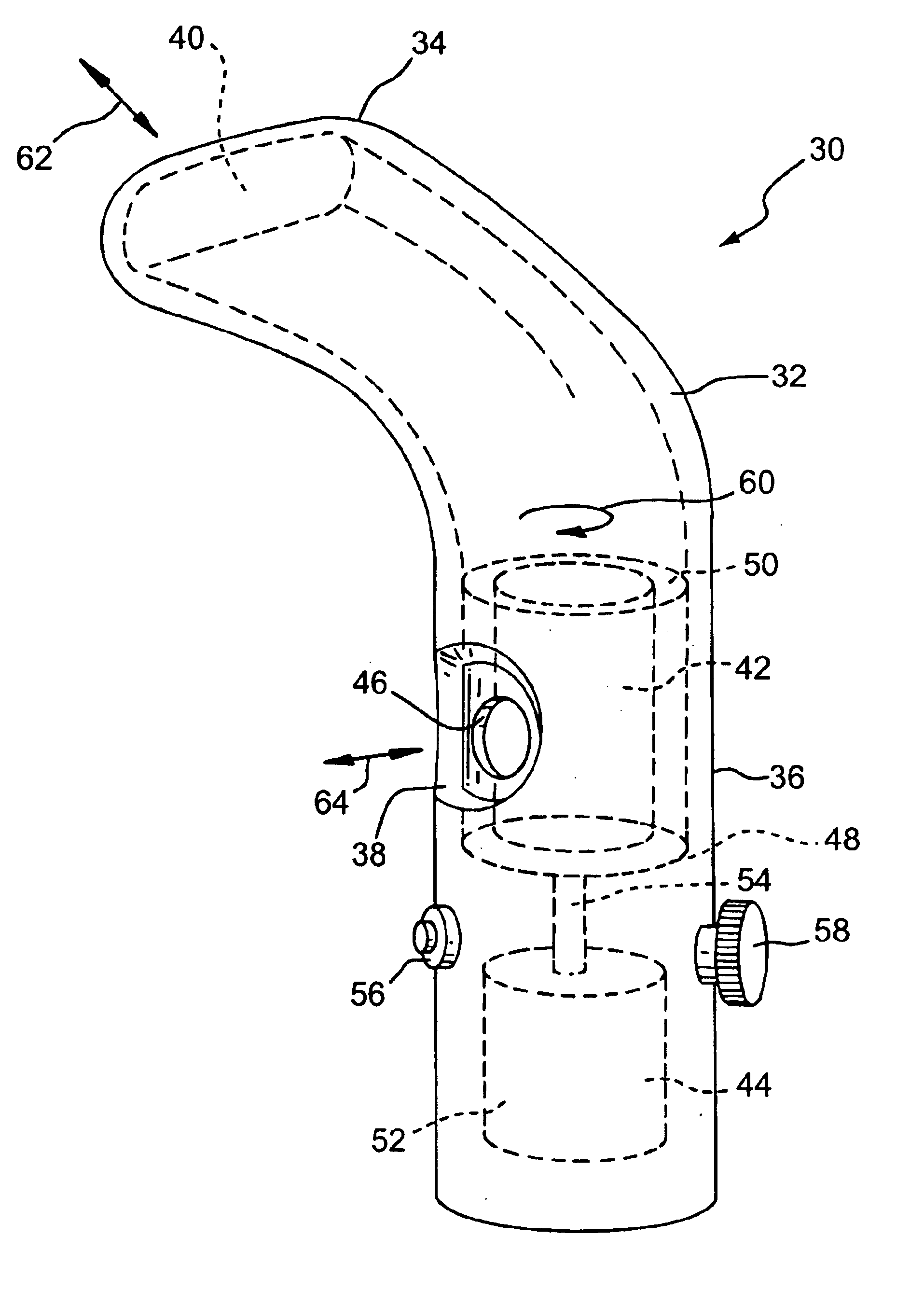
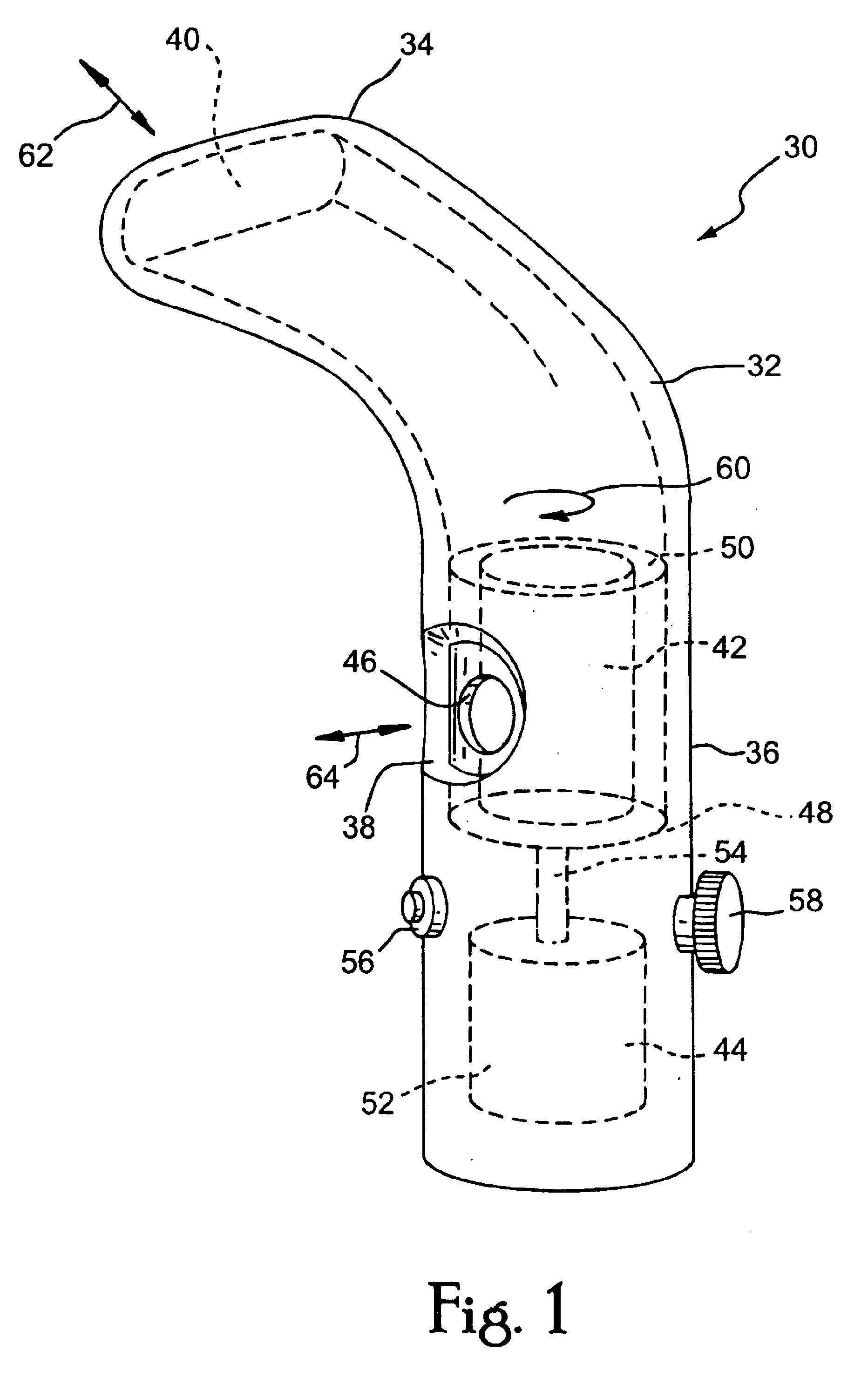
FIG. 1 illustrates a first embodiment of a high frequency pressure oscillation device 30 according to the principles of the present invention. Device 30 includes a patient circuit 32, which, in the illustrated exemplary embodiment, is a generally cylindrical conduit having a mouthpiece end 34 and a breathing gas source coupling end 36. A first port 38 is defined in end 36 so that breathing gas can enter the patient circuit and exhaled gas can vent from the patient circuit. Likewise, a second port 40 is defined in mouthpiece end 34 so that the patient can deliver and receive gas from the source of breathing gas through the patient circuit. In the illustrated embodiment, the source of breathing gas is ambient atmosphere. It is to be understood, however, that the source of breathing gas can be any supply of gas other than ambient atmosphere, such as oxygen or an oxygen mixture provided from a storage tank or a pressure generating device.

A valve 42 is disposed in patient circuit 32 at e...


PUM


Abstract

A high frequency pressure oscillation device and method of providing high frequency pressure oscillations to a patient. The device includes a patient circuit coupling a gas source to an airway of a patient, and a valve disposed in the patient circuit. The valve communicates the gas source with the patient's airway when in a first position and at least partially restricts communication when in a second position. A rotating drive assembly rotates the valve in a first direction such that the valve is alternatively disposed in the first and second positions. This system is capable of delivering positive and negative pressures to the airway of a patient by including a blower as the source of breathing gas. This system is also capable of superimposing a high frequency oscillating pressure signal on another pressure signal by adding a second blower in series with the first blower.

Description

1. Field of the InventionThe present invention pertains to an apparatus and method for providing high frequency variable pressure to a patient to treat a respiratory disorder, and, in particular, to an apparatus and method in which a rotating valve located in the patient circuit creates an oscillating pressure in the flow of gas to or from the patient.2. Description of the Related ArtIt is well known to provide ventilatory assistance to a patient suffering from a respiratory disorder using a pressure support system, such as a ventilator, to deliver a flow of breathing gas at a positive pressure to the patient's respiratory system. For patients with complete respiratory failure, a ventilator or other suitable pressure support device delivers a life supporting flow of breathing gas to the lungs. In less severe situations, the ventilator augments the patient's respiratory function to assist with the patient's work of breathing. In either of these situations, it is not uncommon for the ...

Claims


Application Information

Patent Timeline
Patent Type & Authority Patents(United States)
IPC IPC(8): A61M16/00
CPCA61M16/0096
Inventor HETE, BERNIE F.BOBECK, MICHAEL
Owner RIC INVESTMENTS LLC
Why Eureka
Try Eureka