Ventilatory control system

a control system and ventilation control technology, applied in the direction of valves, respirators, mechanical equipment, etc., can solve the problems of reducing the gain of the plant compartment, affecting the clinical outcome, and significant residual sdb during therapy, and achieving negative effects on clinical outcomes

Active Publication Date: 2007-09-27
PHILIPS RS NORTH AMERICA LLC
View PDF27 Cites 155 Cited by
  • Summary
  • Abstract
  • Description
  • Claims
  • Application Information

AI Technical Summary

Benefits of technology

[0024] These and other objects, features, and characteristics of the present invention, as well as the methods of operation and functions of the related elements of structure and the combination of parts and economies of manufacture, will become more apparent upon consideration of the following description and the appended claims with reference to the accompanying drawings, all of which form a part of this specification, wherein like reference numerals designate corresponding parts in the various figures. It is to be expressly understood, however, that the drawings are for the purpose of illustration and description only and are not intended as a definition of the limits of the invention. As used in the specification and in the claims, the singular form of “a”, “an”, and “the” include plural referents unless the context clearly dictates otherwise.

Problems solved by technology

This can lead to episodes of hyperventilation followed by central apnea (a form of SDB that may have little to do with upper airway collapsibility).
Thus, limiting the decrease in PACO2 (i.e. decreasing the CO2 concentration gradient) with ventilation by increasing the concentration of CO2 in the alveoli lowers the gain of the plant compartment.
However, there are reasons to believe that poor adherence to therapy (i.e., ongoing time spent asleep at the prescribed continuous positive airway pressure (CPAP) is less than target) and significant residual SDB during therapy may have negative consequences regarding clinical outcomes.
Hyperpnea often causes arousals and, thus, degrades sleep quality.
Individuals with obstructive sleep apnea (OSA) that demonstrate CPAP emergent central apneas appear to have issues with both upper airway collapsibility and ventilatory control.

Method used


Image

  • Ventilatory control system
  • Ventilatory control system
  • Ventilatory control system

Examples


Embodiment Construction

[0040] Individuals demonstrating central sleep apnea, Cheyne-Stokes respiration, CPAP emergent central apneas, or other forms of breathing that indicate unstable control of breathing appear to have an elevated loop gain that describes the ventilatory response to a given ventilatory stimulus. The primary contributor to this elevated loop gain is likely an increased sensitivity to carbon dioxide (CO2) by central chemoreceptors (elevated controller gain). The present invention describes a method to counteract this elevated loop gain by lowering the ventilatory plant gain during a state of high respiratory drive and augmenting ventilation during a state of low respiratory drive.

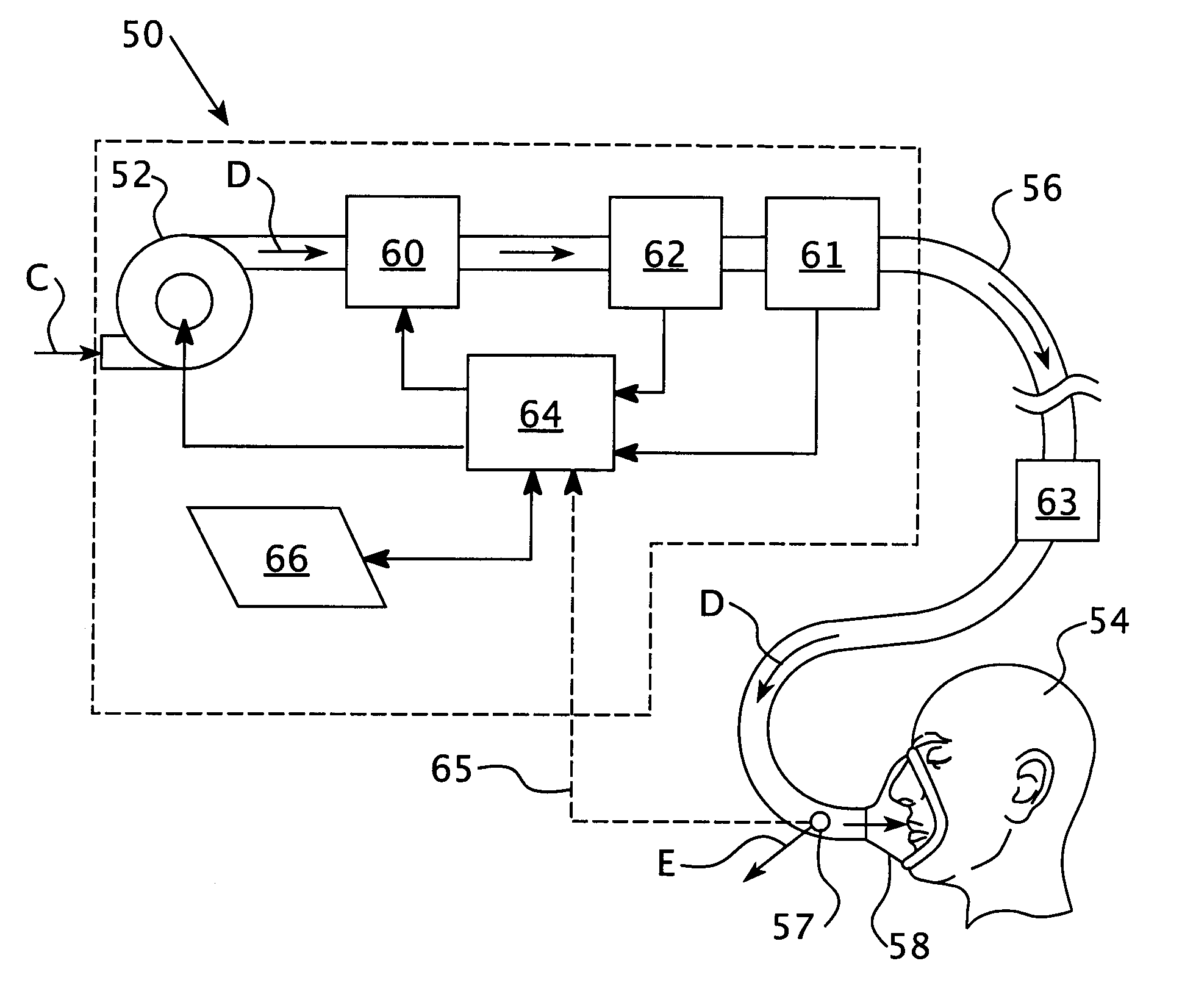
[0041] The functional elements of the apparatus used in the present invention may be similar to those disclosed in the '151 patent. As shown in FIG. 3, a state-dependent positive airway pressure support system 50 includes a gas flow generator 52, such as a blower used in a conventional CPAP or bi-level device, t...


PUM


Abstract

A system is provided for delivering a flow of breathing gas to an airway of a patient. The system includes a pressurizing flow module that generates a pressurized flow of breathing gas and a patient circuit coupled to the pressurizing flow module configured to communicate the flow of breathing gas to an airway of a patient. The system includes a sensor for monitoring a characteristic of a breathing pattern of the patient a controller that communicates with the sensor configured to increase a fraction of inspired carbon dioxide if the characteristic exceeds an upper threshold value and to provide servo-ventilation if the characteristic is less than a lower threshold value. The upper threshold value and the lower threshold value are changed based on the monitored characteristic of the breathing pattern of the patient.

Description

CROSS-REFERENCE TO RELATED APPLICATIONS [0001] This application claims priority under 35 U.S.C. § 119(e) from provisional U.S. patent application No. 60 / 784,127, filed Mar. 20, 2006, the contents of which are incorporated herein by reference.BACKGROUND OF THE INVENTION [0002] 1. Field of the Invention [0003] The present invention relates to the treatment of various forms of sleep disordered breathing, and, more particularly, to treating sleep disordered breathing with an adaptive, state-dependent positive airway pressure system. [0004] 2. Description of the Related Art [0005] Sleep disordered breathing (SDB) is a common condition with important clinical consequences for affected individuals. Physicians and other experts have suggested that SDB exists as a continuum between a pure central apnea (caused by a lost drive to breathe) and a pure obstructive apnea (due to mechanics of the upper airway). Obstructive sleep apnea (OSA) is characterized by repetitive collapse of the upper airw...

Claims


Application Information

Patent Timeline
Patent Type & Authority Applications(United States)
IPC IPC(8): A61M15/00A61M16/00A62B7/04
CPCA61M16/0051A61M16/209A61M16/0075A61M16/1045A61M16/16A61M2016/0036A61M2016/1025A61M2016/103A61M2202/0208A61M2202/0225A61M2205/502A61M2230/10A61M2230/202A61M2230/205A61M2230/432A61M2230/435A61M2230/60A61M16/00A61M16/0045A61M16/0066A61M16/08A61M2230/43Y10S128/914A61M16/0069A61M16/204A61M16/0072A61M16/026
Inventor PITTMAN, STEPHEN D.WITT, ERIK K.BLAKE, STEFANIDA K.
Owner PHILIPS RS NORTH AMERICA LLC
Why Eureka
Try Eureka