

Rib structure for the base of the turning center
A rib and turning technology, which is applied to turning equipment, turning equipment, metal processing equipment, etc., to achieve the effects of improving machining accuracy, preventing local temperature gradients, and reducing thermal displacement
- Summary
- Abstract
- Description
- Claims
- Application Information
AI Technical Summary
Problems solved by technology
Method used
Image

Examples
Embodiment Construction
[0032] Embodiments of the present invention will be described in detail below with reference to the accompanying drawings.
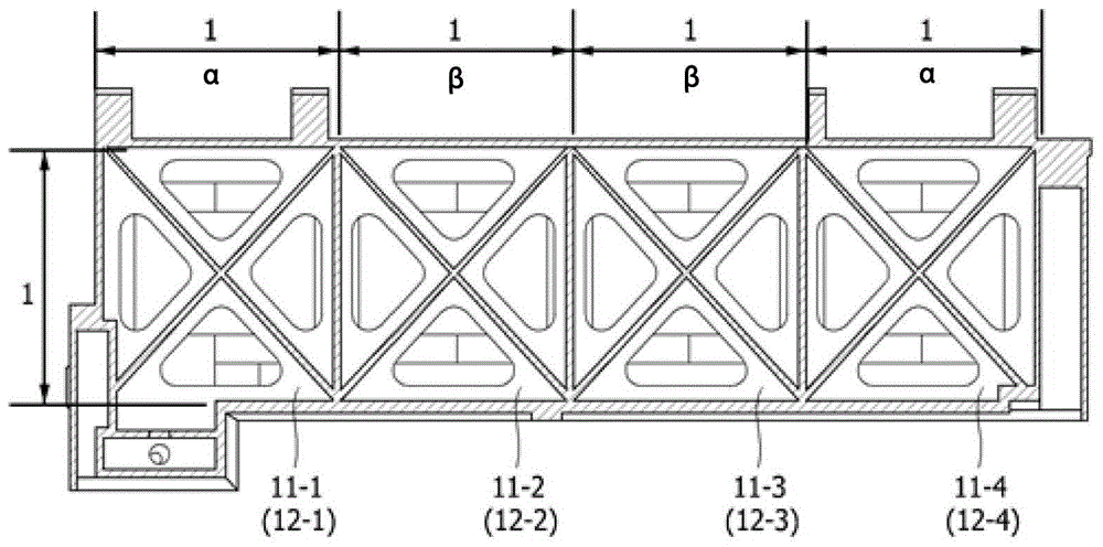
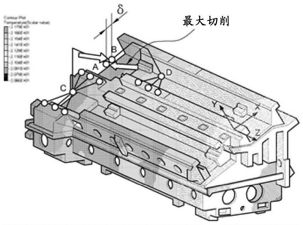
[0033] According to the present invention, in order to reduce the thermal deformation caused by the external temperature change of the turning machining center and improve the static stiffness under the condition of maximum cutting force for high-speed and high-precision machining, the topology optimization (Topology Optimization) should be derived Optimal base rib shape that ensures sufficient rigidity in the direction of maximum cutting force and minimizes relative thermal displacement at the end of the tool and workpiece due to changes in external ambient temperature.
[0034] Figure 4a and Figure 4b It is a diagram for explaining the application principle and design area of topology optimization according to the present invention.
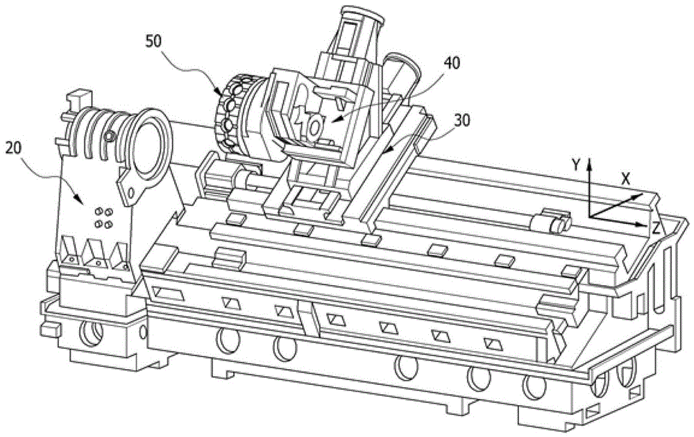
[0035] Such as Figure 4a and Figure 4b As shown, in addition to the installation space (C, D) of the casting ...
PUM
 Abstract
Description
Claims
Application Information