Starter motor assembly with soft start solenoid

A solenoid and starter technology, used in engine starting, electric components, engine components, etc.

Active Publication Date: 2013-05-22
REMY TECHNOLOGIES LLC
View PDF6 Cites 6 Cited by
  • Summary
  • Abstract
  • Description
  • Claims
  • Application Information

AI Technical Summary

Problems solved by technology

However, the holding coil remains energized for a much longer

Method used


Image

  • Starter motor assembly with soft start solenoid
  • Starter motor assembly with soft start solenoid
  • Starter motor assembly with soft start solenoid

Examples


Embodiment Construction

[0033] overall starter structure

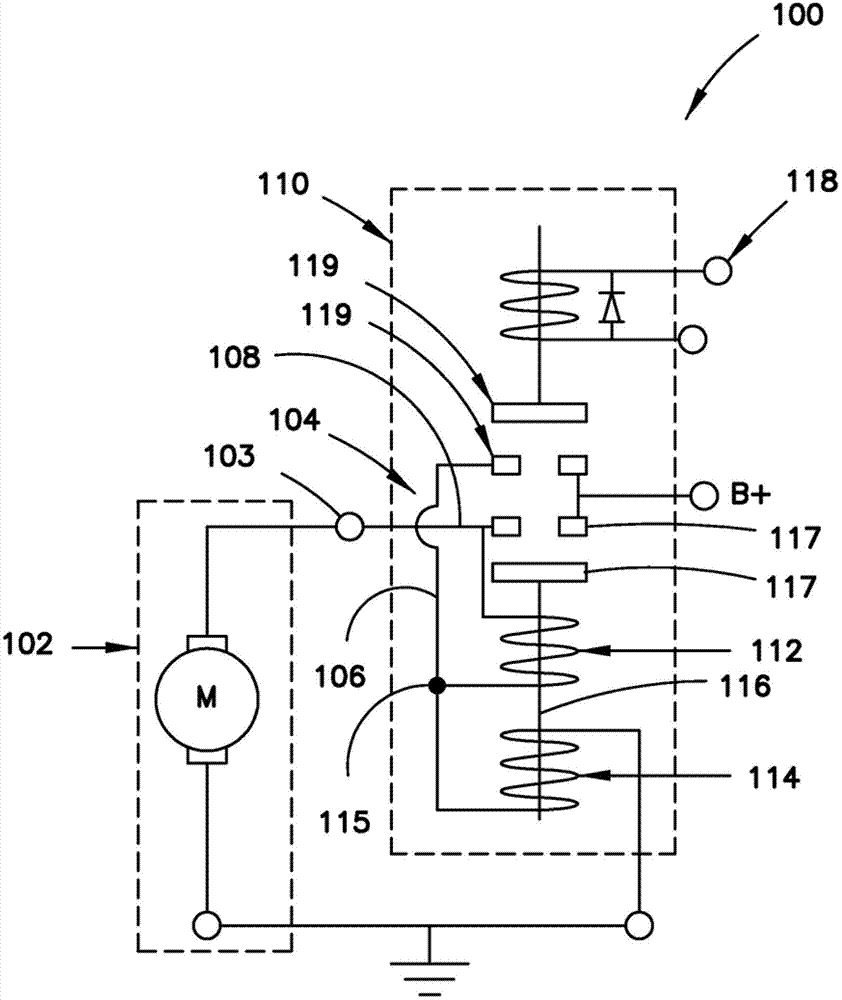
[0034] refer to figure 1 , in at least one embodiment, a starter 100 for a vehicle includes a motor 102 and a solenoid 110 . although figure 1 Not shown, but the starter 100 also includes a drive mechanism and pinion, similar to the conventional starter assembly 200 described above with reference to FIG. 15 . figure 1 The motor 102 in the embodiment of the present invention is disposed in a motor circuit 104 configured to connect the motor to a vehicle battery (not shown) via the B+ terminal. A solenoid 110 is provided in the motor circuit 104 to facilitate connecting the motor to the vehicle battery. The solenoid includes a pull-in coil 112 , a hold coil 114 , a plunger 116 and an ignition switch 118 .

[0035] figure 1 The motor circuit 104 includes a first current path 106 and a second current path 108 configured to provide electrical power to the motor 102 . The first current path 106 starts at the B+ terminal, passes through the co...


PUM


Abstract

A solenoid for a vehicle starter comprises a pull-in coil and a hold-in coil positioned axially adjacent to the pull-in coil. A plunger is positioned within the pull-in coil and configured to move in an axial direction when the pull-in coil is energized. The plunger is separated from a plunger stop in the axial direction by an air gap when the pull-in coil and the hold-in coil are not energized. When the pull-in coil and hold-in coil are energized, a shoulder of the plunger moves in an axial direction toward the plunger stop. The pull-in coil is positioned in the solenoid such that it is removed from the plunger stop in the axial direction. In contrast, the hold-in coil encircles the plunger stop.

Description

technical field [0001] This application relates generally to the field of vehicle starters, and more particularly, to solenoids for starter motor assemblies. Background technique [0002] Starter motor assemblies that assist in starting an engine, such as a vehicle engine, are well known. A conventional starter motor assembly is shown in FIG. 15 . The starter motor assembly 200 of FIG. 15 includes a solenoid 210 , a motor 202 , and a drive mechanism 204 . The solenoid 210 includes a coil 212 that is energized by the battery when the ignition switch is closed. When solenoid 212 is energized, plunger 216 moves in a linear direction, causing shift lever 205 to pivot and forcing pinion 206 to mesh with the ring gear of the vehicle's engine (not shown). When the plunger 216 reaches the plunger stop, the electrical contacts close, thereby connecting the motor 202 to the battery. The energized electric motor 202 then rotates and provides output torque to the drive mechanism 204...

Claims


Application Information

Patent Timeline
IPC IPC(8): H02K7/10
CPCH01H51/065F02N11/087H01F5/02H01H50/20H01H50/44H01H2050/446
Inventor M·D·布拉德菲尔德
Owner REMY TECHNOLOGIES LLC
Why Eureka
Try Eureka