
Light-emitting diode (LED) lamp tube with adjustable angle

A technology of LED lamps and LED chips, applied in the field of LED lamps, can solve problems such as inconvenience of use, and achieve the effect of simple and convenient and optimized illumination angle.

Inactive Publication Date: 2013-05-29
深圳市明连兴光电科技有限公司
View PDF10 Cites 13 Cited by
  • Summary
  • Abstract
  • Description
  • Claims
  • Application Information

AI Technical Summary

Problems solved by technology

[0004] In order to overcome the problem of inconvenient use of the existing LED lamp technology, the present invention provides an angle-adjustable LED lamp

Method used


Image

  • Light-emitting diode (LED) lamp tube with adjustable angle
  • Light-emitting diode (LED) lamp tube with adjustable angle
  • Light-emitting diode (LED) lamp tube with adjustable angle

Examples


Embodiment Construction

[0023] In order to make the object, technical solution and advantages of the present invention more clear, the present invention will be further described in detail below in conjunction with the accompanying drawings and embodiments. It should be understood that the specific embodiments described here are only used to explain the present invention, not to limit the present invention.

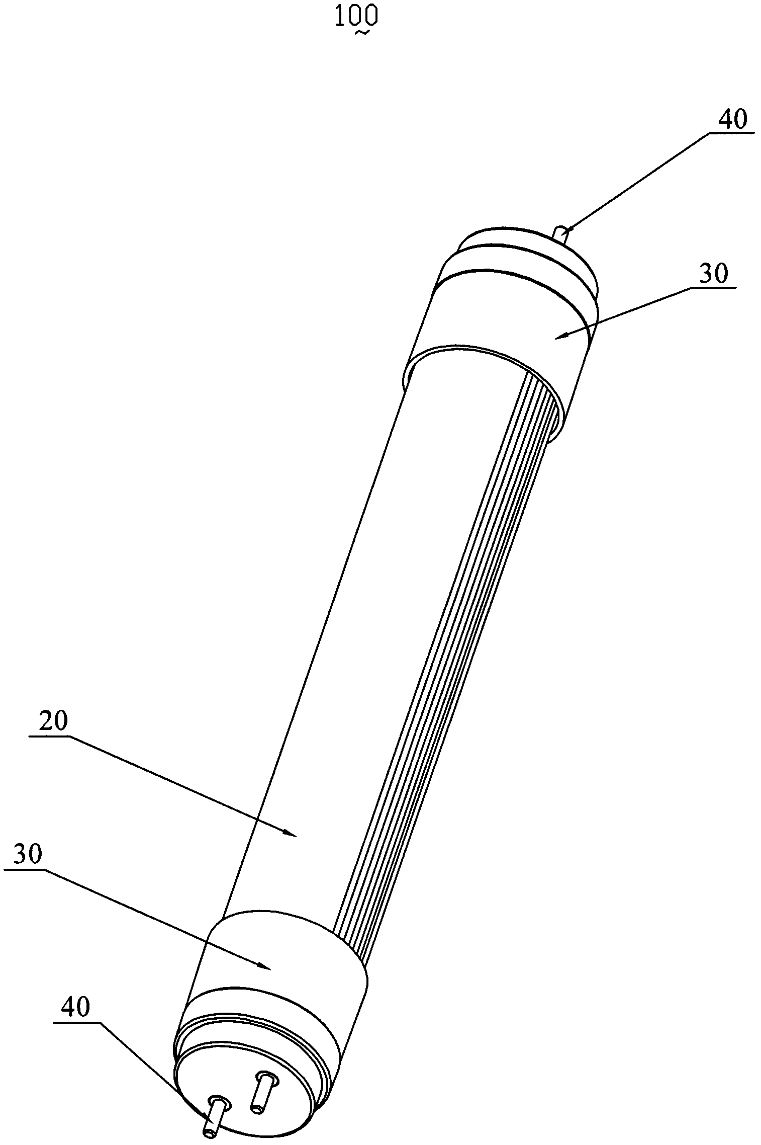
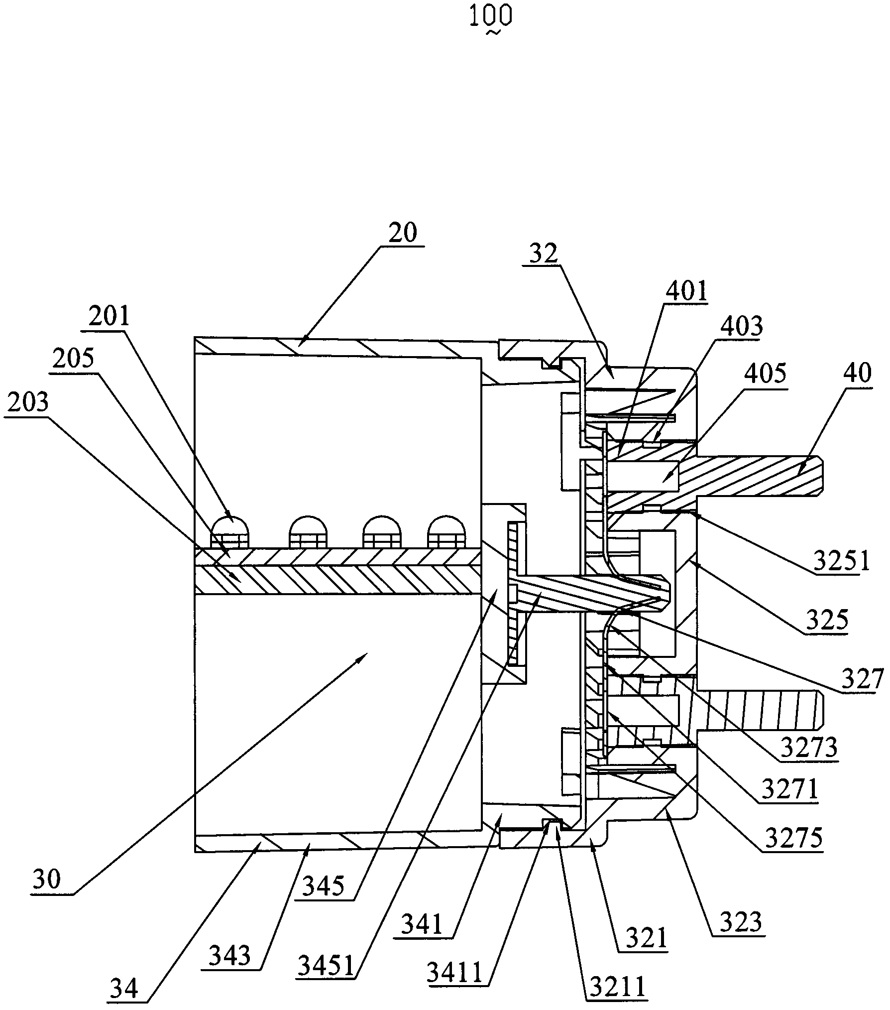
[0024] see figure 2 and image 3 , is the first embodiment of the LED lamp tube 100 of the present invention, which includes four conductive posts 40, two plugs 30 and a lamp tube 20, each plug 30 accommodates and positions two conductive posts 40, and is respectively arranged on the lamp Both ends of the tube 20 are used to fix and adjust the direction of the light-emitting surface of the lamp tube 20 , and the conductive column 40 will provide electric energy for the lamp tube 20 .

[0025] The lamp tube 20 is equipped with an aluminum substrate 205, a plurality of LED chips 201 are arrange...


PUM


Abstract

A light-emitting diode (LED) lamp tube with an adjustable angle comprises a lamp tube body. A plurality of LED chips, at least two conductive columns and two plugs are arranged in the lamp tube body, wherein the two plugs are respectively located at two ends of the lamp tube body, at least one conductive column supplies power needed by the LED chips, the at least two conductive columns are positioned at one end of each plug, and the other end of each plug is connected with one side of the lamp tube body. Each plug comprises a plug fixing shell and a plug rotary piece, wherein the plug rotary piece rotates in a single direction relative to the plug fixing shell to enable the beam angle of the lamp tube body to be optimized.

Description

【Technical field】 [0001] The invention relates to a novel LED lamp tube, in particular to an angle-adjustable LED lamp tube. 【Background technique】 [0002] Nowadays, LED light tubes have been widely used in various occasions, and the same lighting effects as ordinary fluorescent lamps can be achieved by installing LED chips in the light tubes. However, the lighting angle of the LED tube has a certain directivity, so in some special places, such as tunnel lights, its installation position is at a certain angle to the ground, which requires that the irradiation angle of the tunnel lights can be adjusted to facilitate installation achieve the desired direction of illumination. Therefore, in order to better use LED light tubes to meet the lighting angles required in different occasions, it is necessary to overcome the problem of non-adjustable lighting angles. [0003] In order to solve the above problems, there is now a technology that can adjust the luminous angle of the LE...

Claims


Application Information

Patent Timeline
Patent Type & Authority Applications(China)
IPC IPC(8): F21S2/00F21V19/02F21Y101/02F21K9/272F21Y115/10
Inventor 李旭明曹勇
Owner 深圳市明连兴光电科技有限公司
Learn More