
Glue valve and method for controlling same

A technology of glue valve and control ground, applied in the direction of valve operation/release device, valve heating/cooling device, valve details, etc., which can solve problems such as multi-space

Inactive Publication Date: 2013-05-29
FOCKE & CO (GMBH & CO KG)
View PDF6 Cites 0 Cited by
  • Summary
  • Abstract
  • Description
  • Claims
  • Application Information

AI Technical Summary

Problems solved by technology

But these electric heaters require a lot of space and a separate energy supply and cable feeder

Method used


Image

  • Glue valve and method for controlling same
  • Glue valve and method for controlling same
  • Glue valve and method for controlling same

Examples


Embodiment Construction

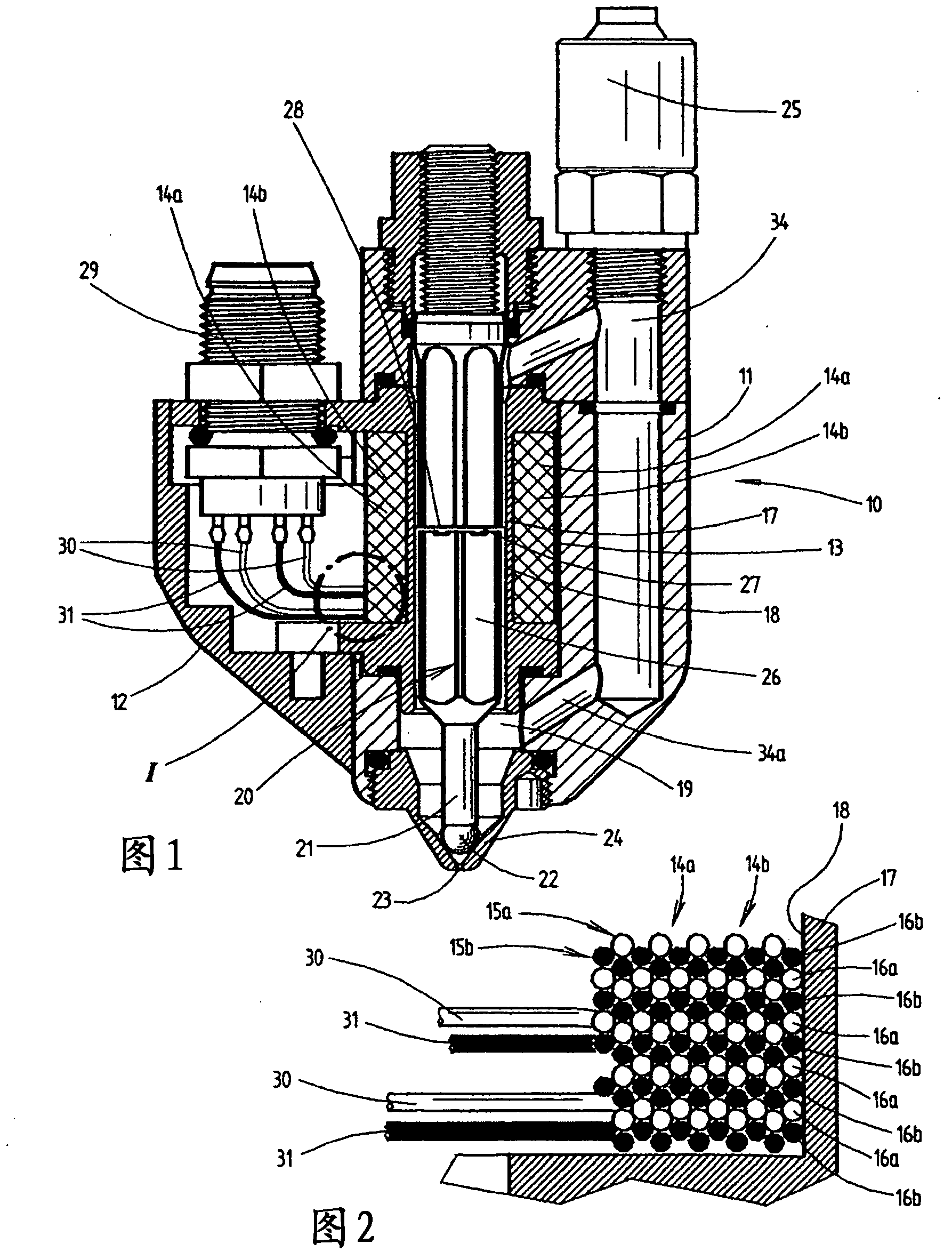
[0017] The glue valve 10 shown in the figures is preferably used to transfer smaller glue portions to the folded flaps of packaging, such as cigarette packs. The valve is designed for high cycle numbers.

[0018] The glue valve 10 includes a valve housing 11 and a plug housing 12 fixed thereon.

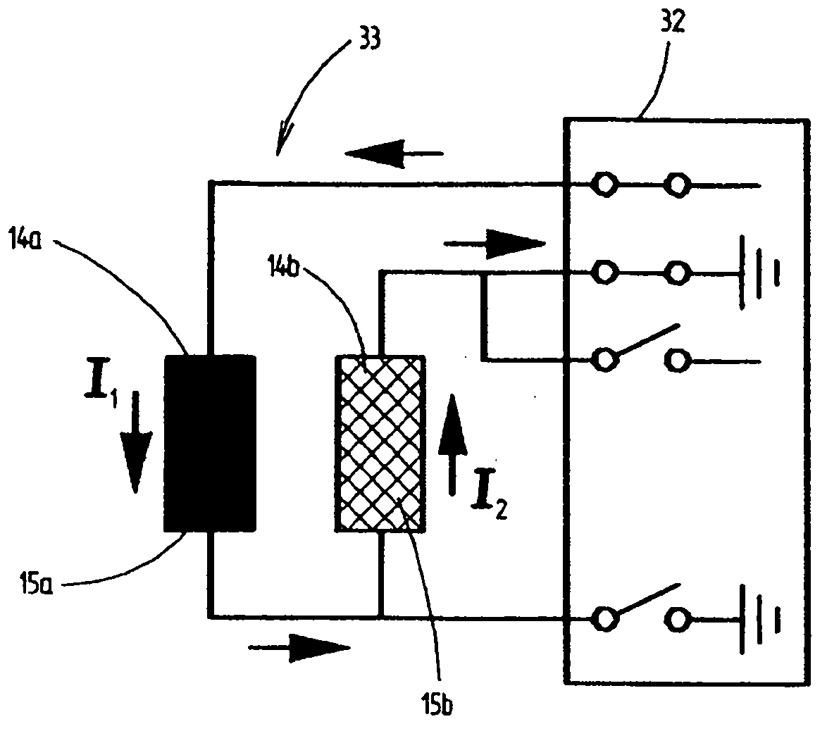
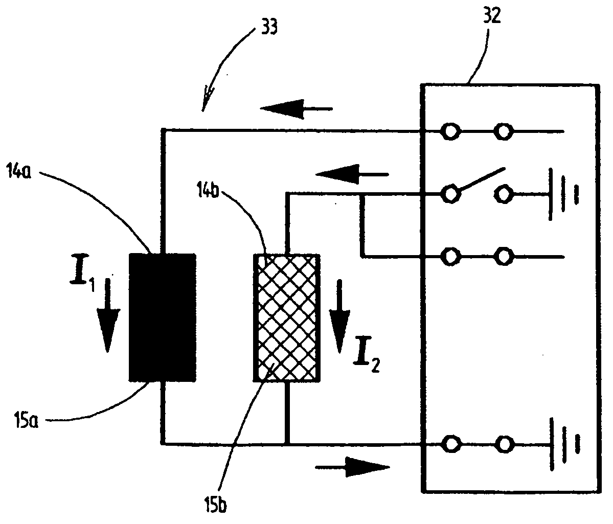
[0019] Inside the valve housing 11 , ie in the valve housing interior 13 , two electromagnets 14 a and 14 b are arranged. In principle, more than two electromagnets can also be used.

[0020] Each electromagnet 14a, 14b has a coil 15a, 15b comprising individual turns 16a, 16b.

[0021] In the present embodiment the coils 15a, 15b are wound on a coil former or coil body 17 . In this case, the coil body has a cylindrical surface 18 in the region of the windings of the coils 15a, 15b. Within the scope of the invention, such a coil body 17 can also be dispensed with, so that the coil is in this case designed without a support.

[0022] The coil body 17 is part of the valve chamber 19...


PUM


Abstract

The invention relates to a glue valve and a method for controlling same, comprising a closing organ (20) which can be actuated in a controllable manner and with which the valve (10) can be switched back and forth between an open position and a closed position, and comprising a heat source (14a, 14b) with which glue, in particular hot glue, can be heated, said glue being conductable through the glue valve (10). The valve (10) has at least two electromagnets (14a, 14a) which can be supplied with electric current independently of each other, which are arranged along a common axis, and each of which comprises at least one spool (15a, 15b), said closing organ (20) being actuatable with said electromagnets and the glue that can be conducted through the valve (10) being heatable with said electromagnets. Both electromagnets (14a, 14b) are positioned and designed such that the magnetic effects of the spools (15a, 15b) of both electromagnets (14a, 14b) either strengthen or at least partially, preferably completely, neutralize each other along the common axis dependent on the current supply to said magnets.

Description

technical field [0001] The present invention relates to a glue valve comprising: a controllably operable locking mechanism, with which the valve can be switched back and forth between an open position and a closed position; The guided rubber is heated. In addition, the invention also relates to a method for controlling the glue valve. Background technique [0002] Glue valves are known in which the locking mechanism is switched and actuated by means of an electromagnet. Glue valves are also known in which the supplied glue, usually so-called hotmelt, is heated inside the valve. Some separate electric heaters are used for this purpose. However, these electric heaters require a lot of space and a separate energy supply and cable feeder. In addition, usually the electric heater is arranged spatially away from the valve chamber. This spatial distance makes it necessary for the electric heater to operate at high temperatures. Contents of the invention [0003] Proceeding ...

Claims


Application Information

Patent Timeline
Patent Type & Authority Applications(China)
IPC IPC(8): B05C5/02B05C11/10B05C5/00F16K31/08F16K31/06F16K49/00B31B1/62B65B51/02B05B1/30B31B50/62
CPCB05C5/0204B05C5/001F16K31/082F16K31/0679B65B51/023F16K31/0662F16K49/002B05B1/3053B65B19/22B05C11/1028B05C5/0225
Inventor M-D·施特根W·罗韦德尔J·施纳肯贝格
Owner FOCKE & CO (GMBH & CO KG)
Learn More